
My 40m transmitter doesn’t have any frills at all. It is CW only and so far I’ve been listening to its signal on the receiver that I’ve been using with it. This works fine as the transmitting aerial is completely separate from the receiving aerial and the transmitter power is only around one watt.
So I’ve added a sidetone oscillator to the transmitter so that I can hear what I’m sending for when I do proper transmit/receive switching with one aerial.
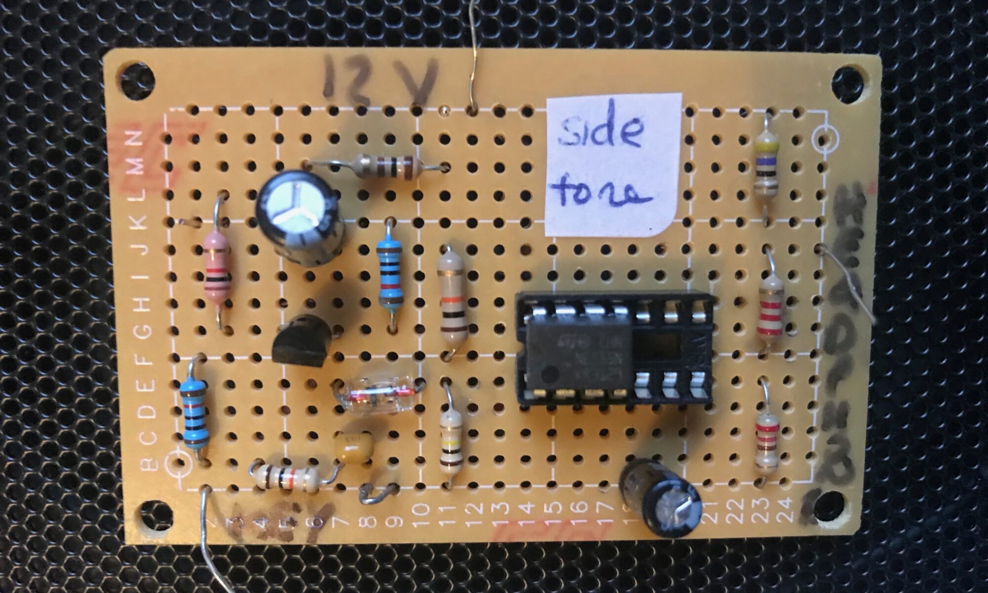
I looked at PIC-based and LM386-based solutions, but decided on the circuit in chapter 1 of “Experimental Methods in RF Design” by Hayward et al (EMRFD). The circuit is based on a 555 timer. It beats other circuits I looked at because it is simple to build, uses through-hole components and is plenty loud enough for my ageing ears. Although it’s a square wave oscillator it sounds fine. I may add an LPF as the harmonics are louder than the fundamental.
I didn’t have all the components specified in EMRFD so I substituted others that seem to work fine.
Here’s the circuit and layout as ‘designed’ in EAGLE.

 The circuit works as follows. The morse key is attached to the JP1-KEY pin and when the key is keyed it grounds R2 making Q1 switch on. The 555 timer is configured as a multivibrator triggered through D1. The square wave output goes to JP2-HEADPHONE pin.
I will replace R7 with a trimmer pot as the current value makes the output too loud even for me.
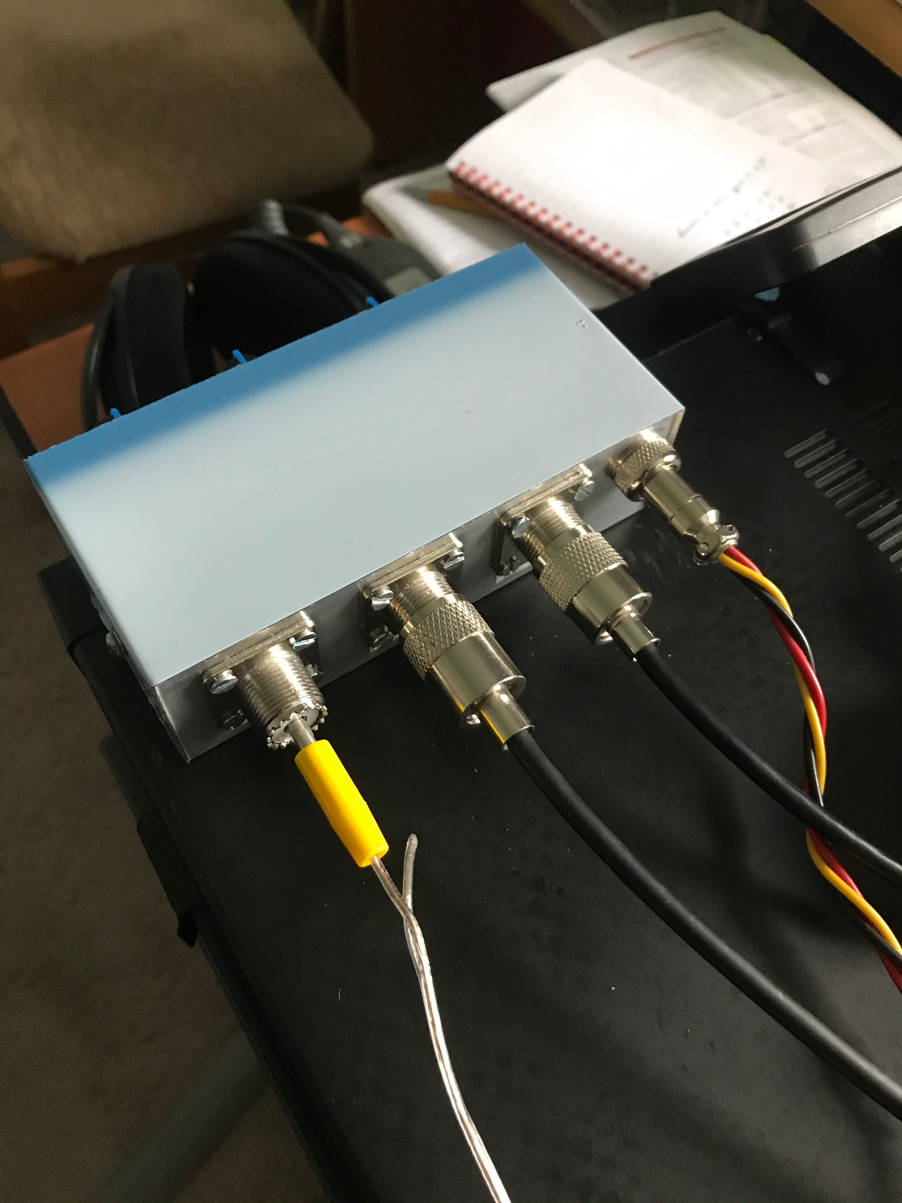
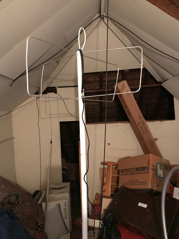
 The nanoVNA sweep is quite slow so you need to have a fairly wide sweep span so that you can see the dip in SWR when you are tuning the loop. So you set the centre frequency and then the span and then tune until you see the dip disappearing off one end. Then you fine-tune the loop and end up with the dip at the centre frequency. The loop is now tuned as in the photo above.


