
My home-brew 40m transmitter only handles a straight key at the moment, but I use a paddle. I currently use a separate keyer but this is a bit clumsy. I found a simple keyer circuit that should do the job. The keyer is by N1HFX: see http://www.rason.org/Projects/cwkeyer/cwkeyer.htm. Thanks, Mike!
The keyer is not iambic, but that’s ok for me as I usually use a single lever paddle. When I’m using a dual paddle key I don’t squeeze.
I didn’t have the exact components so I tweaked the design to cope with what I did have. Here is the new schematic and layout. I guess you shouldn’t mix IC families, but it works!


The circuit works like this. Firstly, the oscillator.
R2 is the variable resistor between SPEED_POT_1 and SPEED_POT_2.
Assume pins 5 and 6 are 0 V, and C1 has no charge. Pin 4 will be at 5 V.
C1 will get charged through R2 and R1. 0nce most of the 5 V is across C1, pins 1 and 2 will be at 0 V and pin 3 will change to 5 V. Pin 3 is directly connected to pins 5 and 6 so pin 4 will go to 0 V. C1 will discharge and once discharged enough pins 1 and 2 will be at 5 V and pin 3 will become 0 V which is where we came in.
The speed of the oscillation depends on C1, R2 and R1. R2 is variable and is used to change the speed. The speed could be calculated by using the RC curve and seeing where it hits logic high and low. But I decided to do the calculations in MATLAB using these scripts. This gives a plot for R2:

This suggests you can’t key faster than about 27 WPM. This isn’t yet a problem for me as I can barely do 17 WPM.
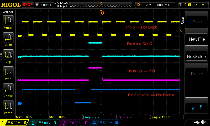
The keying logic is like this. Assume the both paddles are up initially. The logic levels are like this for dots:
^ marks dot clock transition to high
CLK  N0R8     N0R9     D    Q    DOT Paddle
-    1        x        0    x    up
^    1        0        0    0    up
-    0        0        1    0    down
^    0        0        1    1    down
-    0        1        0    1    down
^    0        1        0    0    down
-    0        0        1    0    down
^    0        0        1    1    down
-    0        1        0    1    down
^    0        1        0    0    down
and so on giving equally spaced dots
-    1        1        0    0    up
^    1        0        0    0    up
and so on giving no dots.
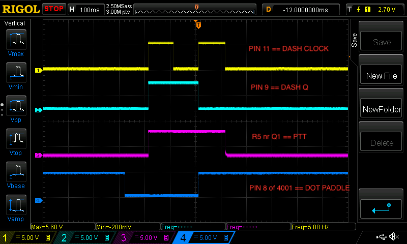
Or, less analytically: the dot paddle grounds one input to the NOR gate and the output of this is clocked into the dot flip-flop. The Q output of the flip-flop is fed back into the other NOR gate input. This gives clocked dots.

All this works fine. Breadboarding was fun, but I made the mistake of putting it on pad board and the soldering was onerous — there’s just too many connections between the two chips hidden under the board. Next time I’ll brush up my coding skills and use a micro-controller.
One Reply to “Simple Morse Keyer”