WSPR Transmitter–Code and Development

The WSPR Transmitter has, of course, firmware code. The D1 Mini runs most of the code, with the PIC12F1640 running the LPF driver. I hold the source code in a git repository on a local server.

The D1 Mini code was developed on a Raspberry Pi 4 mostly using Arduino CLI and vi. I used a couple of helper shell scripts (ardcomp and ardup below) to compile and upload. There are a couple of libraries required: ESP8266 and HCRTC. wspr_rtc_ad9850.ino takes about 19s to compile on Raspberry Pi 4, which is about twice as fast as a Raspberry Pi 3B+. 

ardcomp: 
arduino-cli compile --fqbn esp8266:esp8266:d1_mini_clone $*
ardup: 
arduino-cli upload -p /dev/ttyUSB0 --fqbn esp8266:esp8266:d1_mini_clone $*

I used a Raspberry Pi 4 because I like to protect the USB ports on expensive computers from the possibility of smoke due to any misadventures I may cause. See my previous post.

The PIC code was developed using MPLAB on an HP14S laptop running Windows 10. The USB port is protected (hopefully) by the PICkit 3 dongle that is needed to program the PIC. I’m not a great fan of MPLAB but, once you realise you can ignore all the marketing, it suffices.

The source is in this ZIP file. It’s at the stage it was when I made smoke. The code was working–it was the power supply circuit that was faulty!

My previous posts explain the code.
WSPR Transmitter LPF Control

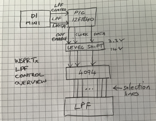
The WSPR transmitter needs an LPF to help make the transmission clean with low-level harmonics. I chose an RV3YF LPF board which has LPFs for each ham band. The band to be filtered is chosen by raising the voltage on the correct pin in a row of pins. The WSPR transmitter uses a separate PIC controller to select the correct pin. I chose a separate PIC so that the LPF and its control could perhaps be put into a module together. I haven’t actually done that but it’s possible.

WSPR Tx LPF Control Overview

As you can see the D1 Mini tells the PIC which pin to select. The PIC uses a 4094 to convert from serial to parallel. 

I had intended that the interface between the D1 Mini and the PIC be an I2C connexion. But I couldn’t work out how to make the PIC act as an I2C slave. There are plenty of examples of I2C masters, but slaves are thin on the ground. So the interface is a home-brew protocol. Luckily I had just enough pins available on the PIC. The LPF_CONTROL line is raised by the D1 Mini when it is going to configure the LPF. It then raises and lowers the LPF_DATA line the appropriate number of times. Then the LPF_CONTROL line is lowered to denote the end of configuration. The PIC sits waiting for the LPF_CONTROL to go high and counts the number of transitions of LPF_DATA seen before LPF_CONTROL goes low.

On the output side of the PIC, my RV3YF LPF needs 14V to reliably switch the relays. So the 4094 has a 14V supply. When LPF_CONTROL goes low the PIC lowers the 4094 output enable pin. It then clocks out the number denoting the band to the 4094 thus selecting the correct LPF band. The PIC then raises the 4094 output enable pin and the band is selected on the LPF module.

I found it impossible to debug the D1/PIC interface on a breadboard as the signals were too noisy. So I decided to put the circuit straight to strip board. This solved the  debug problem and it worked happily when powered from the bench supply. I then added some circuitry to supply the 14V from an off-the-shelf buck converter. Unfortunately (or probably my own foolish fault), when I was adapting the power circuitry I managed to make (at least) the RTC module go up on smoke. I still don’t know why it did. 

I’ll post the code and the strip board layout next time.