
I bought an X-Phase QRM eliminator a while back, tried it out with a receiver and was quite impressed with its performance. It’s only recently that I’ve connected it to a transceiver because without care it is easy to damage the unit when transmitting.
QRM eliminators have been around for many years. I was recently looking at an old Practical Wireless from 1989 and S.E.M. were selling one then in the adverts at the back of the magazine. (And, yes, we used dots in abbreviations back then). If you were to be picky you might say it should be called a QRN eliminator, but it isn’t. I quite like the idea of an actual QRM eliminator though I’m not sure how you could implement it.

A QRM eliminator works like this: signals from the main aerial are mixed with signals from a noise aerial. The signals from the noise aerial can be shifted in phase. The idea being that you mix the main signal with the noise signal 180º out of phase. If the signals are the same you’ll just get a zero signal. But if the main signal comprises a good signal and some noise signals and the noise signal is predominantly the noise signals, you’ll end up with just the good signal. Of course, to make this work you need to be able to make the noise signals from the main and noise aerials be the same amplitude so the QRM eliminator has controls to adjust the gain of each. As you want the signals to be 180º out of phase there is also a control to adjust the phase.

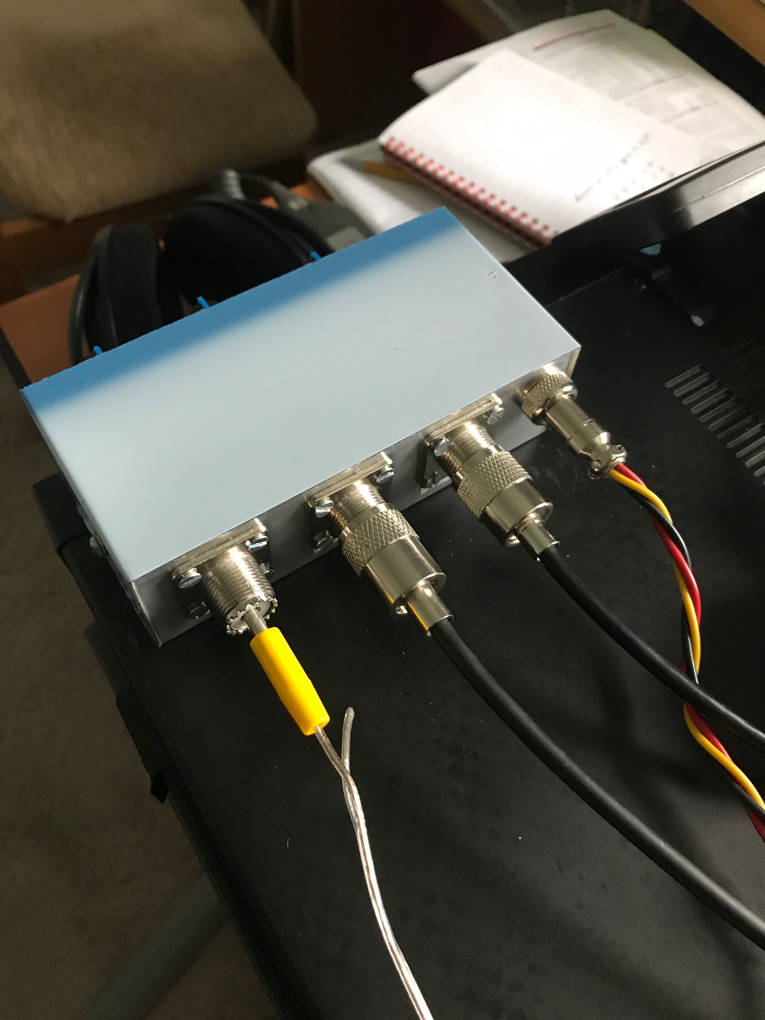
The three blue knobs in the photo are these controls.
There are several QRM eliminators on the market. I got mine from Poland on eBay from the seller urbania2. The unit is solidly built in a neat aluminium box with pleasant to use control knobs and strong connexions on the back.
The instructions are in a quaint mixture of Polish and English but I found them understandable enough as a circuit diagram is included.
I have done some quick tests on 20m with the unit and it seems to be able to reduce the background noise by about 3 S-points as shown on my TS590S transceiver. I also made some measurements using received FT8 signals. This showed an increase of about 4dB in the signal strength of CQ signals as reported by JTDX over 15 minutes with the QRM eliminator being on each even minute and off each odd minute. None of this testing was particularly scientific though. I was using a 4m length of loudspeaker wire as the noise aerial, just lying on the floor of the shack.

I mentioned that it’s easy to damage the unit when transmitting. It has three wires. Red and black are for the DC supply, and the yellow wire is for the PTT. When grounded the eliminator passes the main signal straight through avoiding the damage.
This Is how I connected my TS590S. The EXT-AT connector on the TS590S provides a nominal 13.8V DC. So I used pins 1 and 6 to power the Eliminator. I got the EXT-AT plug from an eBay supplier asia_uk.

The remote connector on the TS590S isn’t particularly well documented, but connecting the yellow wire from the Eliminator to pin 4 works, but only if menu 53 on the TS590S is set to 2. Pin 2 on the remote connector, the common terminal needs to be grounded so I connected it to pin 3 on the EXT-AT seeing it was spare. I got the required 7-pin DIN plug from RS Components.

If I’m using an external atu and swr meter where does the eliminator sit in the line?
It’s quite a while back I wrote about the QRM Eliminator but I think I put it closest to the aerial. It’s bypassed when you’re transmitting (or else it gets damaged) so when you’re tuning it doesn’t matter where it is.