Tuning a loop with nanoVNA

One of the aerials I use is a small transmit loop. These loops have a really narrow bandwidth which is good and bad. Good in that you get much less noise, bad in that you have to keep retuning. If you stick to one frequency such as with some digital modes it is ok as you don’t have to retune too much. Other modes such as SSB and CW are less easy to use with a loop.

You can tune the loop by transmitting into it and tuning the loop until the SWR is good. This is a bit anti-social as you can be transmitting for quite some time as you tweak the tuning. I used to use a noise bridge which works quite well as long as your ears don’t get tired. The nanoVNA offers easier, more visual way of tuning. 

nanoVNA loop tuningThe nanoVNA sweep is quite slow so you need to have a fairly wide sweep span so that you can see the dip in SWR when you are tuning the loop. So you set the centre frequency and then the span and then tune until you see the dip disappearing off one end. Then you fine-tune the loop and end up with the dip at the centre frequency. The loop is now tuned as in the photo above.

This works fine with the nanoVNA GUI, but as I am nearly always running a Mac when I’m on the radio I wrote a Matlab script to do the tuning. The script is run and sets the centre frequency and span for you.

Here’s a sample tuning transcript (user input in green):

>> ajfTuneLoop
connect: Serial-/dev/tty.usbmodem4001
status:  open
press RETURN when loop is connected to ch0
Frequency to tune to (MHz) ? 7.074
tune loop for dip at the marker, press RETURN when tuned ok
close
>> 

The script is ajfTuneLoop.m.

The nanoVNA and MATLAB

The nanoVNA is a cheap but usable vector network analyser. It is good value and very useful for all sorts of RF design and radio ham activities.   I suggest you buy a nanoVNA from a reputable dealer as there are plenty of clones which don’t work as well as the original. The model I have has a tiny screen which I can read adequately but it isn’t as comfortable as reading a computer screen. The NanoVNA is a touchscreen device so you need to tap on tiny text to do anything. Again, this is possible but far from comfortable for those of us with ageing eyes. There’s also a bit of screen reflection.

nanoVNA

The nanoVNA can be driven from a PC using a program called nanoVNA-saver which is pretty good. Unfortunately it runs on Microsoft Windows and as I don’t have a PC running Microsoft Windows I have to run it in a VirtualBox VM on my Mac Mini. This works but is a bit clunky and to be honest my Mac mini is a bit long in the tooth and struggles to run virtualised Windows 10 at a reasonable speed.

There is a cross-platform solution based on Python which looks promising. It uses Homebrew on MacOS which clashes with MacPorts which I use. I tried to make it work under MacPorts but fell into the usual maze of incompatible library versions causing the make to fail. So I gave up as I want to play with electronics and not software building. [Update: Rudi, DL5FA kindly helped with this and it looks like the Python Virtual Environment will help when I’ve got the time to try again.]

MATLAB to the rescue! — alex_m has created some MATLAB scripts which allow you to interrogate and control the nanoVNA from MATLAB. Thanks Alex! So if you have MATLAB this may be useful. If you don’t you may be able to convert much of this to Octave but it does use the MATLAB RF Toolbox so you may end up doing a lot of work.  Alex’s scripts produce LogMag, Smith Chart and TDR Step Response graphs. 

Here’s a graph showing my 40m LPF characteristics made using Alex’s scripts.

40m LPF LogMag

I’ve written a couple of scripts based on Alex’s work which I think makes using the nanoVNA easier. Both scripts need an edit to configure the serial link to the nanoVNA. You’ll need Alex’s code too.

The first script ajfCalibrate.m calibrates the nanoVNA for a particular sweep on the S11 port. You have to do this before every measurement that changes the sweep values, so you do it a lot. Here’s how it looks in the MATLAB console. The inputs are in italics.

>> ajfCalibrate
connect: Serial-/dev/tty.usbmodem4001
status: open
Sweep start (MHz)? 7
Sweep stop (MHz) ? 7.2
Calibrating...
press RETURN when S11 is open
press RETURN when S11 is shorted
press RETURN when S11 has 50 ohm load
Save [0-4]? 4
close
>>

The second script ajfVSWR.m produces a chart of VSWR against frequency. Most radio hams are happier with this than the LogMag chart preferred by RF designers. 

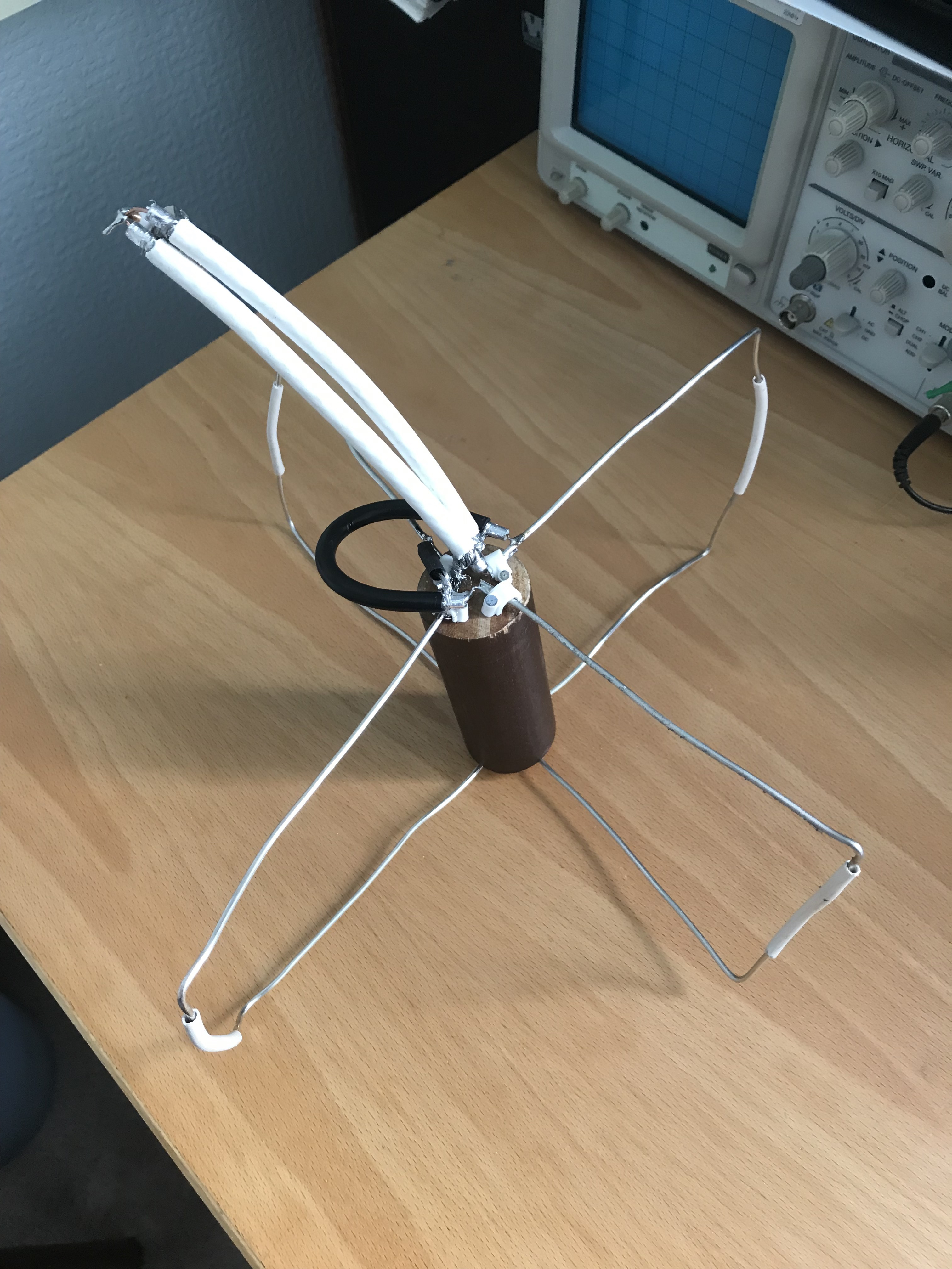
I used ajfVSWR to measure my small transmitting loop tuned to the 40m FT8 frequency. As expected it shows the narrow bandwidth in low VSWR that is the drawback of small transmitting loops. 

40m FT8 VSWR

The graph can be zoomed in MATLAB and have data cursors added to show more details.

40m FT8 VSWR 2

The VSWR could be lower. I think I left a metal step-ladder in the attic which is affecting the loop.

ajf? My initials.

Cebik Moxons in the Attic

I now have both 2m and 70cm Cebik Moxons in the attic separated using a HA8LFK diplexer. After trying out the 70cm aerial it is clear that it needs a preamp to pick up any signals. Partly this is due to the poor coax I’m using and I should replace it with something better. So I’ve added an M-100 preamp powered from a shack PSU through a pair of bias-tees.

I tried bypass the M-100 with a relay but I haven’t been able to source a relay that works well at UHF. Usually the non-connected path is only 20 or 30 dB down on the connected path. This is not safe enough to protect the preamp, so that’s another reason for giving up transmitting for now. I’m pretty sure the aerials will not be good enough for decent transmissions and I would end up being the recipient of pleas from an OM: “I got the Mike, Zero and Yankee, your callsign again again please…”.

The setup looks like this scribble from my lab book:

Scribble form lab book

Unfortunately the M-100 draws 55mA which is 5mA too high for the built-in bias-tee in the SDRplay RSP2. The RSP2 is my receiver of choice at the moment. More on that later.

Cebik Moxons, SDRplay and satellites

There was a pass of the AO-91 satellite over my location today and I listened to the ham radio operators operating through it.

I used my home-built Cebik Moxon aerials which are located in my attic and the nice SDRplay RSP2.

Cebik Moxon in attic

Here’s a screenshot of SDRuno displaying the AO-91 signals for those of you who don’t think the Doppler effect is real.

Doppler on Waterfall

You can easily see the received signal changing frequency as the satellite hurtles past.

This is what it sounds like. 

AO-92-12.09-Wednesday-May-8-2019-20190508-1209.m4a

It was recorded using Audio Hijack Pro from a Microsoft Remote Desktop session of SDRuno on a Dell XP workstation. Apologies for the over-driven audio — I was concentrating on receiving rather than recording.

HA8LFK Diplexer Characterisation

I decided to build or buy a diplexer to communicate with LEO (low earth orbit) satellites that use cross-band operation.

Some of the satellites in LEO are U/V or V/U. U/V means the satellite receives at UHF but transmits at VHF. V/U is the other way around.

My space aerials are in the attic and there are only two cables going from the shack to the attic. One thick cable is used solely for HF, and the other thinner cable is used for higher bands, 6m, 2m and 70cm.

A diplexer allows the use of different frequencies on the same cable. In this case it allows both VHF and UHF aerials to be used on the same cable. The diplexer has one input (from the transceiver) and two outputs (one to the VHF aerial and one to the UHF aerial) when transmitting. The diplexer blocks VHF signals going to the UHF output, and also blocks UHF signals going to the VHF output. In this way the transmit power goes where it is most wanted, that is, to the appropriate aerial. 

On receive the same ports are used but there are two inputs (one from each aerial) and one output (to the transceiver).

I decided not to built a diplexer for VHF/UHF operation as fiddling with inductors at those frequencies can be a bit hit-or-miss unless you use SMD components. It’s much easier to buy one, especially for those of us who are challenged when building VHF and UHF inductors. There are a few diplexers on offer, and I chose one on eBay from HA8LFK. It seems well built and works fine. The 50W limit certainly won’t affect me just now as the highest power I can send on VHF/UHF is 5W. One drawback may be that the sockets are SMA and my shack mostly uses BNC for VHF and above.

Diplexer

I have characterised this diplexer by sending sine waves of various frequencies through its transmit path and measuring the outputs. The signals came from my WaveTek model 1062 sweep generator and were measured at my HP 54615B scope. I used SMA/BNC adapters and short BNC cables to connect the diplexer to the test equipment.

Ha8lfk diplexer graph

As you can see the sweep generator signal is almost flat. The VHF port peaks a little lower than the 2m band. The UHF port peaks a little lower than the UHF band. Neither seems significant.

The insertion loss on transmit is 1.45dB at 2m, and 1.79dB at 70cm.

I didn’t make a graph for receive but did measure the insertion losses: 0.72dB at 2m, and 1.24dB at 70cm. This surprised me as I would have thought the diplexer would be symmetric, but it appears not.

Now to use it in anger …

70cms Cebik Moxon Aerial for LEO Satellites

The 70cms (435MHz) version of the Cebik Moxon is now built and shows an SWR of 1.1 in the shack as measured with my AW07A antenna analyser. Hopefully this SWR will not change too much when I put in in the attic.

The elements are made out of #12 AWG wire from RS Components. The sizes are as specified in Cebik’s original article published in the ARRL QST in August 2001 “A Simple Fixed Antenna for VHF/UHF Satellite Work”. The phasing line is built as for the 2m version using RG59U coax cable from BitsBox only using a length for the 70cm band. The matching line is made from old 75Ω cable TV cable again at 70cm band length. The elements and lines are explained in my earlier post about ‘Building the 2m Cebik Moxon’.

The elements are stapled to an old wooden curtain pole to keep the driven elements and reflectors apart. At the ‘floating’ end they are kept apart using the insulation from old multi-core telephone cable and the shaft from cotton buds. I’ll hot-glue these in place once the aerial is in the attic. The distance between these floating ends is the most critical in the whole aerial.

LL0foAdTSrmGQ6ghONMY2A

I plan to use this aerial with the 2m version and suitable diplexers to communicate with U/V or V/U LEO satellites. Watch this space!

SSTV Award

The International Space Station transmitted some slow-scan TV images during February 2019. My 2m Cebik Moxon in the attic was easily able to receive these images even at quite low elevations. No need to be outside pointing a Yagi in the February chill!

ISS NOTA SSTV PD120 20190210 164147
SSTV Image from ISS

The images I received can be seen in the ARISS SSTV Gallery. You’ll need to put in my callsign: MM0GYG.

They handed out awards too.

Diplome

Great fun!

Satellite Aerial Link Budget

I’ve had a little luck transmitting to a satellite. I’m using packet as I can use the 2m Cebik Moxon aerial for both transmit and receive. To see if the ISS should be able to hear my signals I wrote a link budget program in Racket. There’s a few assumptions in it but it seems to confirm the ISS should have no problem hearing me on 2m. The program shows:

Transmit power (W)?
5
Frequency (MHz)?
145.825
Elevation (°)?
40
Transmit power:   5 W (36.99 dBm)
Frequency:        145.825 MHz
Satellite height: 403 km
Elevation angle:  40°

Satellite is 5396 km away
Signal at satellite is 9 dB above noise

This seems borne out as I do receive what seem to be digipeated packets just after I transmit them. But I can’t confirm on the ISS site that they are real and not just an echo from somewhere.

70cms doesn’t look as good:

Transmit power (W)?
5
Frequency (MHz)?
435.255
Elevation (°)?
40
Transmit power:   5 W (36.99 dBm)
Frequency:        435.255 MHz
Satellite height: 403 km
Elevation angle:  40°

Satellite is 5396 km away
Signal at satellite is -0 dB above noise

Increasing the power to 25W might work:

Transmit power (W)?
25
Frequency (MHz)?
435.255
Elevation (°)?
40
Transmit power:   25 W (43.98 dBm)
Frequency:        435.255 MHz
Satellite height: 403 km
Elevation angle:  40°

Satellite is 5396 km away
Signal at satellite is 7 dB above noise

I’m currently building the 70cms version and will try some FM voice contacts.

Here’s the link budget program:

#lang racket
; link budget for Cebik Moxon in attic
; Andy Fletcher Jan 9, 2019 

;
; definitions
;
(define (get_user_input prompt)
  (begin
    (displayln prompt)
    (string->number (read-line))))

(define (log10 n)
  (/ (log n) (log 10)))

(define (watts2dbm w)
  (* 10 (log10 (* w 1000))))

(define (degrees2radians d)
  (* (/ pi 180) d))

(define (square x)
  (* x x))

; distance to satellite in km
(define (satellite_distance e_degrees height)
  (let* ([e (degrees2radians e_degrees)]
         [earth_radius 6371]    ; kms
         [r (+ height earth_radius)] ; distance between geocentre and satellite
         )
    (sqrt (+ (square (* earth_radius (cos e))) (square r) (- (square earth_radius)) (- (* earth_radius (cos e)))))))

; free space path loss
(define (fspl f d)
  (- (+ (* 20 (log10 f)) (* 20 (log10 d)) 32.45)))

;
; execute
;
(let* (
       [ptx_watts (get_user_input "Transmit power (W)?")]
       [f         (get_user_input "Frequency (MHz)?")]
       [e_degrees (get_user_input "Elevation (°)?")]
       [h 403]               ; satellite height in kms
       [cable_loss -3.55]    ; measured dB
       [tx_gain 6.0]         ; Cebik Moxon modelled gain in dB
       [roof_loss -6.0]      ; assumed loss of signal going through the roof in dB
       [rx_gain 2.0]         ; assumed receive gain at satellite in dB
       [sat_max_sens 124.0]  ; assumed satellite maximum sensitivity in dBm
       [distance_to_satellite (satellite_distance e_degrees h)]
       [ptx (watts2dbm ptx_watts)]
       )
  (begin
    (printf "Transmit power:   ~a W (~a dBm)\n" ptx_watts (~r ptx #:min-width 1 #:precision 2))
    (printf "Frequency:        ~a MHz\n" f)
    (printf "Satellite height: ~a km\n" (~r h #:min-width 1 #:precision 0))
    (printf "Elevation angle:  ~a°\n" e_degrees)
    (printf "\nSatellite is ~a km away\n" (~r distance_to_satellite #:min-width 1 #:precision 0))
    (printf "Signal at satellite is ~a dB above noise\n"
            (~r  (+ ptx cable_loss tx_gain roof_loss (fspl f distance_to_satellite) rx_gain sat_max_sens) #:min-width 1 #:precision 0))))

Building the 2m Cebik Moxon

The Cebik Moxon is made up of four driven elements, two reflectors, a phasing line and a matching line.

The matching line is needed to match the 25Ω impedance presented by the aerial to the 50Ω impedance expected by the coax feed to the radio. It is made up of parallel quarter-wave lengths of 75Ω cable. I modelled this in an excellent application SimSmith by AE6TY to see how critical its length is (the answer being not very much). The SWR is 1.125 at 351mm, and only rises to 1.13 at 330mm and 354.5mm.

I worked out the velocity factor of the RG59U 75Ω cable (bought from Bitsbox who were very prompt and helpful but didn’t know its velocity factor) by building a TDR out of a circuit to make a fast pulse and my HP54615B scope. As usual Alan, W2AEW came to the rescue with this video #88: Cheap and simple TDR using an oscilloscope and 74AC14 Schmitt Trigger Inverter.

Here are my sums to work out the velocity factor of the RG59U cable measured with the TDR circuit.

5m takes 48.8ns between peaks, so the signal takes \frac{48.8}{2} = 24.4ns  to go 5m which is 4.88ns/m, so the speed is  \frac{1}{4.88ns/m} = 204.918 \times 10^{6} m/s, so the Velocity Factor, VF = \frac{204.918 \times 10^{6}}{c} = 0.683.

Using EE Toolkit on iPhone, in air ¼ \lambda is 513.7mm at 145.9MHz.

So ¼ \lambda should be 513.7 x VF = 350.857mm.

SmithMatching37z5line
SimSmith Matching Line

The phasing line is just a quarter wavelength of 50Ω cable which feeds the other element 90° out of phase from the first. Here’s an XY scope picture of the phasing.

Lissajous of phasing

It should be a bit more upright but I think that is probably due to the way I’m connecting it to the scope rather than the phasing line itself.

Now the bit I am particularly bad at: putting it all together.

I made the elements out of 6mm aluminium round tube. The tube is easy to cut with a hacksaw and to bend using a pipe bender. The matching section and phasing line are connected to the rods using solder tags and screws. The driven elements and reflectors are kept apart by whittled pea sticks. This distance between the driven elements and the reflectors is the most critical measurement. The pea sticks are held in place with shrink wrap and friction. The elements are hot-glued to a plastic drain pipe. This is not very robust, but works as long as the aerial isn’t disturbed too much. I’ll have to fix this properly if I want to move the aerial from the attic to the garden.

Cebik in attic
Aerial in attic

Cebik Moxon Aerial and Packet

When used with my FT–60 transceiver handheld, which is FM only, the Cebik Moxon picks up satellites AO–85, NO–84, AO–91, AO–92 and ISS SSTV. I don’t know enough about satellites to know if it’s getting good signals but I can hear many voice stations, amongst them G0VHS, EA7IFT, G0IIQ, OH1ON, EB2DJ, G0FGX, PE1NIL.

Using DireWolf and Xastir as described in my FT60 PTT page, we get

NO 84 Map
A map of stations