FT–60 PTT
The schematic shows a PTT circuit for connecting an FT–60 VHF/UHF transceiver to a Raspberry Pi 3B+ acting as a TNC. The circuit grounds the PTT while the TNC is transmitting. It disconnects the PTT from ground when the TNC stops transmitting or after about 10s.
The FT–60 is connected to the PTT and audio using a Yaesu CT–44 adapter. The adapter is not strictly necessary but it allows for the audio to be connected using a standard 3.5mm jack to jack cable. The PTT circuit is connected via twisted pair to the 2.5mm socket on the CT–44. I used a mono 2.5mm jack. The audio is captured and played using a 33051D USB Soundcard.
The Raspberry Pi is expected to raise GPIO 25 while transmitting. This is done by running Direwolf by WB2OSZ, and Xastir. Both are installed in the usual way using apt-get. The Direwolf configuration needs changed to use the soundcard. I changed it as follows:
ADEVICE plughw:1.0 plughw:1.0
PTT GPIO 25
MYCALL MM0GYG
You find out the numbers to put into the ADEVICE line by calling aplay -l and arecord -l in a shell. Note that the GPIO number is not the pin number (which on a 3B+ is 22) but the GPIO number.
You use them by first starting direwolf in a termina1 using direwolf -p, and once that is up start xastir in another terminal. Direwolf annoyingly flashes its text making it hard to read. But it should show something like this:
Dire Wolf version 1.3
Includes optional support for:  gpsd

Reading config file direwolf.conf
Audio device for both receive and transmit: plughw:1,0  (channel 0)
Channel 0: 1200 baud, AFSK 1200 & 2200 Hz, E+, 44100 sample rate / 3.
Ready to accept AGW client application 0 on port 8000 ...
Ready to accept KISS client application on port 8001 ...
Virtual KISS TNC is available on /dev/pts/1
WARNING - Dire Wolf will hang eventually if nothing is reading from it.
Created symlink /tmp/kisstnc -> /dev/pts/1
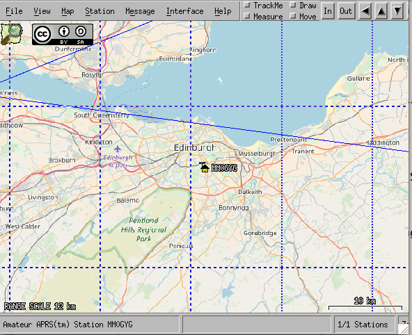
Xastir is configured following the help screens you get in Xastir itself: menu Help>Help Index. You need to configure the station, which is just your callsign and location. Also you need to add an interface to /tmp/kisstnc and activate it. It may help to choose some map tiles to show your area. Around Edinburgh the Mapnik tiles seem good, although I notice they don’t show the new bridge.

The Raspberry Pi provides a 5V supply to the timing circuit which draws 6.45mA when idle and 5mA when transmitting.
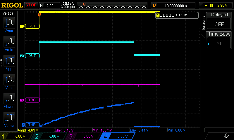
The timing circuit is a 555 timer configured in monostable mode. It is held with RESET low until the TNC starts transmitting. The 555 RESET is raised high by the TNC. C1 briefly charges and allows Q1 to conduct causing TRIG to pulse low. This makes the 555 raise OUT (labelled Q in the schematic). The normal case is when the TNC stops transmitting and it drops RESET which causes the 555 to also drop OUT. If the TNC transmits too long the voltage at 555 THR reaches \(\frac{2}{3}\) VCC and so the 555 drops OUT.
The 555 OUT going high causes Q2 to conduct thus grounding PTT in the FT–60.
The case where the circuit times out is shown in these traces:

I designed this circuit as I couldn’t figure out the circuit suggested in the Raspberry Pi Direwolf notes (see man direwolf to locate them) and I don’t like building circuits I don’t understand. There are probably better ways to do it, but it works for me.