This is a drop-in replacement for a Colpitt’s oscillator as the local oscillator for the mixer in a direct conversion receiver using a NE602. So it has no frills — it just generates a square wave at the required frequencies. The tuning is done with a rotary encoder. The receiver I want it for works on the CW part of the 40m band so the VFO tunes from 7.000 MHz to 7.020 MHz. An LED lights when a frequency limit has been hit. The encoder button is used to toggle the tuning rate between fast (1000 Hz per click) and slow (100 Hz per click). These can be changed to any pair of values, as can the frequency limits.
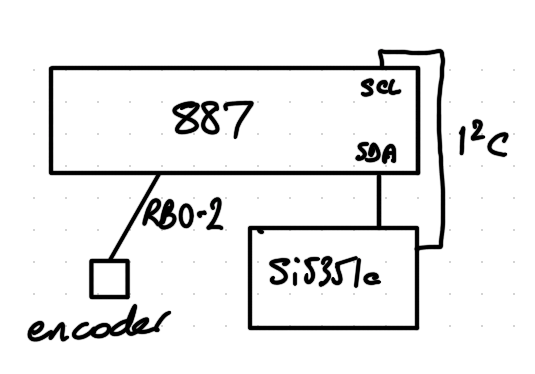
A Si5351a synthesiser is used to generate the square wave. It is controlled by a PIC micro-controller.

I wanted to use a small 8-pin PIC for this to make the VFO have a small footprint. I chose a PIC12F1840 which has the I2C built-in needed to drive the Si5351a. But I found that I couldn’t program this PIC with my ageing PICkit2. So I tried my even more ancient K150 programmer — no joy here either. So I’ve had to use a PIC16F887 for now — even though it must be twenty times bigger. I considered bit-banging the I2C with a PIC12F683 or a PIC12F688, but it looks pretty onerous and I don’t want to spend my time chasing I2C errors. It may be the time has come to move on from PICs though I haven’t seen any alternatives that appeal yet.
The code traps encoder turns as interrupts and works out which way the encoder is turning. The debounced encoder button and frequency changes are done in the main (endless) loop. The Si5351a I2C is driven using a port of Hans Summer’s Si5351a Arduino demo. Thanks Hans! I’m also using one of Hans’ Si5351a module kits. I ‘trimmed’ the 27 MHz crystal by changing the value of SI_XTAL_FREQ in si5351a.h to 27003934 which gave the expected frequencies as seen on my ancient RACAL-DANA 9916 frequency counter.
Here are the source files and make file to build the VFO.
I haven’t tried this in the receiver yet, but it’s hopefully useful as it is.
Sometimes an encoder turn isn’t seen, but this doesn’t seem to be too obvious in use. I intend to fix that when I port the code to whatever PIC replacement I choose.

Hi,
I want to add an LCD Display to this project. Would you be so kind as to assist me in displaying the frequency on a lcd display using the 16f887 pic?
i don’t have website.