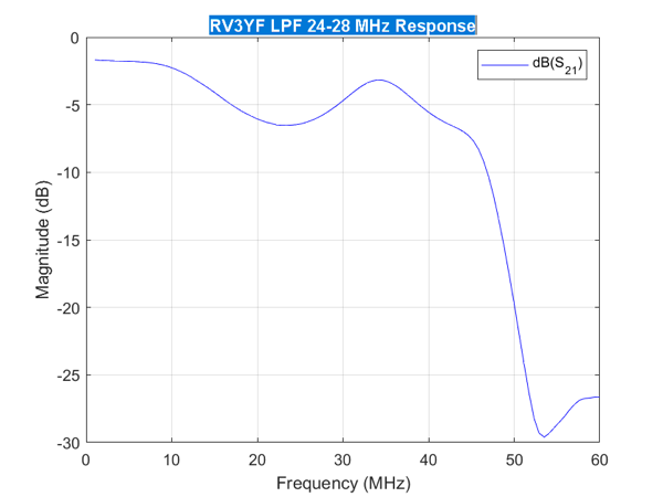
Switchable LPF Response

The switchable LPF for my WSPR Transmitter finally arrived and I’ve made some response graphs to test how it performs.
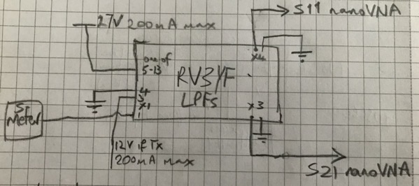
Test setup for Switchable LPF

The obvious bit of test kit to check out the LPFs is my nanoVNA. I suggest you buy a nanoVNA from a reputable dealer as there are plenty of clones which don’t work as well as the original.

The test setup is above. The 27 V in the drawing can go as low as 13.8 V, but will not work at any lower voltage. 

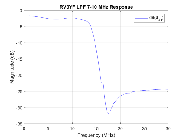
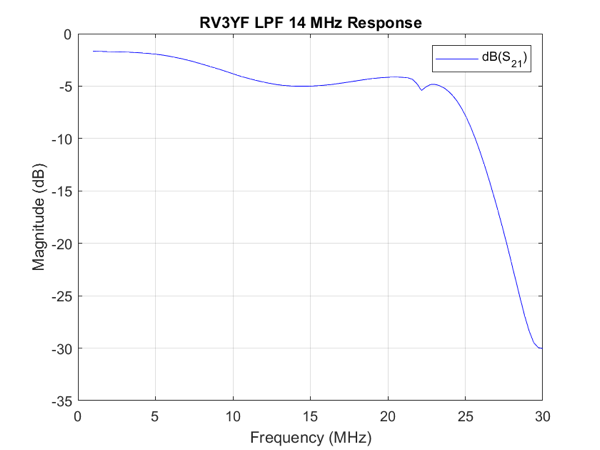
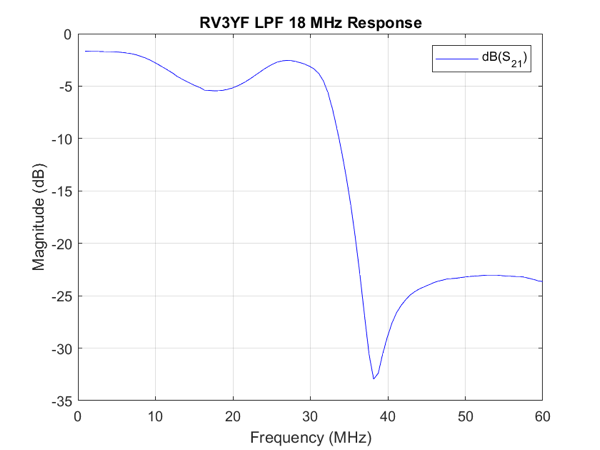
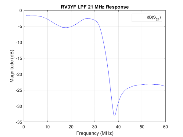
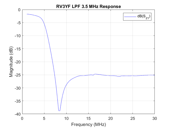
As I’ve mentioned before I find the small screen on the nanoVNA difficult to control with my clumsy hands. So I wrote another simple MATLAB script ajfLogMagS21 to drive the nanoVNA to get the response charts. The calibration done as before using my ajfCalibrate MATLAB script. The LPFs will attenuate the harmonics by 25 dB which will be enough for my feeble WSPR output.
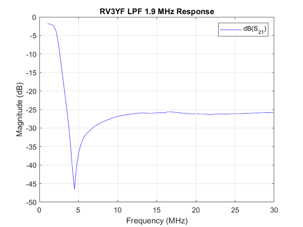
RV3YF LPF 1 9 MHz Response

RV3YF LPF 3 5 MHz Response

RV3YF LPF 7 10 MHz Response

RV3YF LPF 14 MHz Response

RV3YF LPF 18 MHz Response


RV3YF LPF 21 MHz Response

RV3YF LPF 24 28 MHz Response

The next step is work out how to drive the switching of the bands. First thoughts are to send commands via I2C and have something convert that to a 13.8-27 V signal on the appropriate pin. I2C is attractive as I already have an I2C bus in the WSPR Transmitter.
Yet Another WSPR Transmitter

I have joined the ranks of the many who have built a WSPR Transmitter. Why? Mostly so I can have a bit of fun. The problem is difficult enough to be interesting but not so complex as to become boring. Having said that there’s a lot involved.

I can transmit WSPR with my TS590S and presumably any other off-the-shelf transceiver. But these all have fan noise so I wouldn’t want to run them overnight. So the transmitter will be able to be used to test propagation overnight.

But mostly I’ve made it to have the fun of making it.

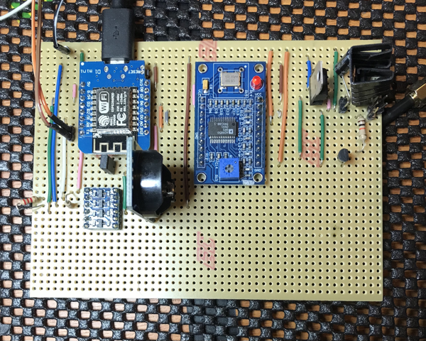
The transmitter cycles through the amateur bands from 80m to 10m optionally transmitting on each band. An RTC module (DS3231 I2C Real Time Clock Module) is used to keep track of the real time. An AD9850 DDS Signal Generator Module produces the RF signal. Both of these are controlled by a D1 Mini ESP8266 Dev Board. The ESP8266 does all the encoding of the WSPR tones and decides when to send them. The signal from the AD9850 is run through a power amp (10W linear HF PA from QRP Labs) then through an appropriate LPF to the aerial.

WSPR Transmitter Picture

Currently I’ve only had it on air on the 40m band as I only have a home-brew 40m LPF to hand. This works fine and the signals are being picked up in Europe ok. I’m getting a switchable LPF for the other bands but it’s taking a while to arrive from Russia. However the transmitter works on every band as my TS590S close to the transmitter can pick up the stray signals when I run it into a dummy load. The signals are decoded fine using WSJT-X.

More details later.