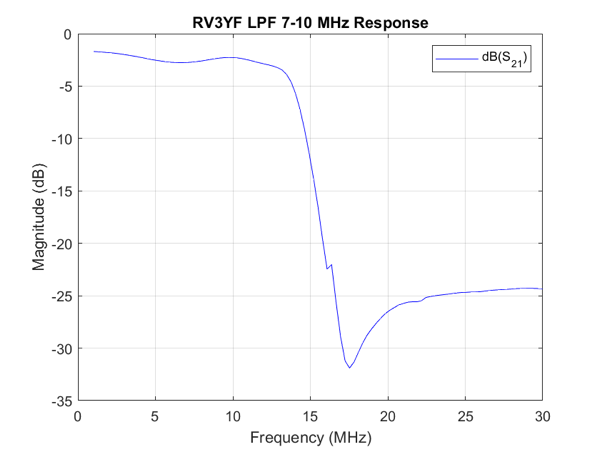
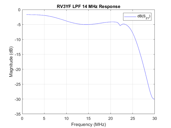
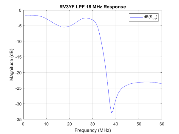
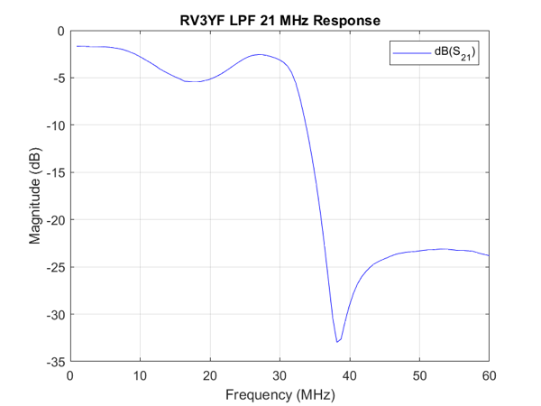
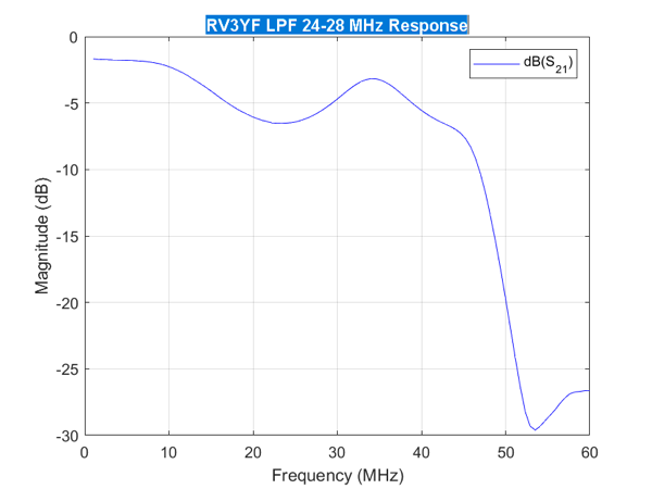
The switchable LPF for my WSPR Transmitter finally arrived and I’ve made some response graphs to test how it performs.
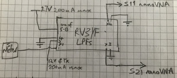
The obvious bit of test kit to check out the LPFs is my nanoVNA. I suggest you buy a nanoVNA from a reputable dealer as there are plenty of clones which don’t work as well as the original.
The test setup is above. The 27 V in the drawing can go as low as 13.8 V, but will not work at any lower voltage.
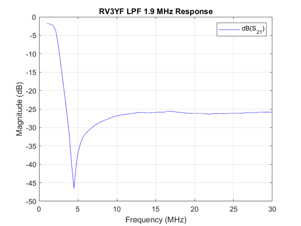
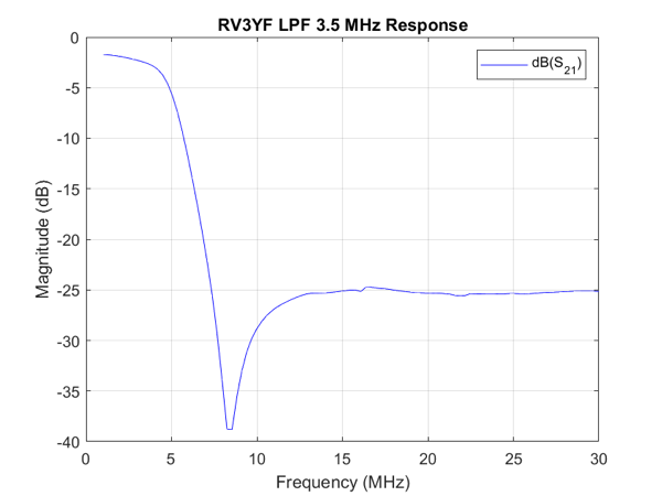
As I’ve mentioned before I find the small screen on the nanoVNA difficult to control with my clumsy hands. So I wrote another simple MATLAB script ajfLogMagS21 to drive the nanoVNA to get the response charts. The calibration done as before using my ajfCalibrate MATLAB script. The LPFs will attenuate the harmonics by 25 dB which will be enough for my feeble WSPR output.
The next step is work out how to drive the switching of the bands. First thoughts are to send commands via I2C and have something convert that to a 13.8-27 V signal on the appropriate pin. I2C is attractive as I already have an I2C bus in the WSPR Transmitter.
