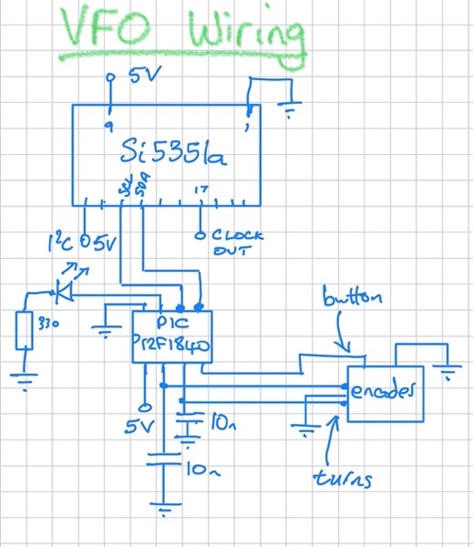
To recap: this is a no-frills VFO intended as a drop-in replacement for a Colpitt’s oscillator in a Direct Conversion receiver. It allows the frequency to be changed within limits set in the code and allows the tuning to be toggled between fast and slow. An LED lights if a frequency limit is reached.
I decided what to use instead of the PICs I usually choose. The answer is: … more modern PICs! A lot of the competition are modules which makes them bigger.
I bought a PICkit 3 which seems to be a lot cheaper than when I last looked. This allows me to program a PIC12F1840 which is much smaller than a PIC16F887. So I have ported the PIC16F887 Si5351a VFO code to that PIC. I have improved the encoder turn handling. With the encoder I’m using I needed to debounce by adding capacitors to ground. The tuning speed is toggled with a button in the encoder. It may be nicer to have a switch instead, perhaps a DIP switch for the tuning as holding down the button while tuning is a bit clumsy.

The PIC12F1840 has a sleep instruction so the code now does all the encoder turn processing in the ISR. The main loop goes to sleep and all that is done in it is to change the frequency of the Si5351a. So the PIC is asleep nearly all the time. It only wakes up when the encoder is turned. The Si5351a is always on, though, as it is generating the clock that the received RF signal is beating against.
A separate button (or DIP switch) allows the user to change the amount the frequency changes each turn. The VFO uses 30 mA when sleeping and 40 mA when the encoder is turning. I don’t know what the Colpitt’s oscillator took.
Here’s the code.
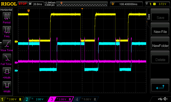
While I was debugging the code I took the following screenshot:

The yellow and blue are decoder turn voltages. The pink is the LED used for debug. It goes high if the code is on the ISR. As you can see it enters the ISR at every encoder turn change. The reason I’d had to go to these lengths to see what was going on was that I’d assumed that the interrupt-on-change flag was for all changes, but it isn’t. There are separate flags for rises and falls. Moral: always read the data sheet!
The footprint of the VFO is only slightly larger than the Colpitt’s oscillator and if that used a beefier variable capacitor the new VFO would be smaller. I’m hopeful it will be useful in a lot of projects.

Grazie.