SDRplay and dodgy USB connection

I had thought that my SDRplay RSP2 was dead because none of my computers would recognise it. But I noticed that it was still drawing current from the USB port when attached and 50 mA seemed reasonable.

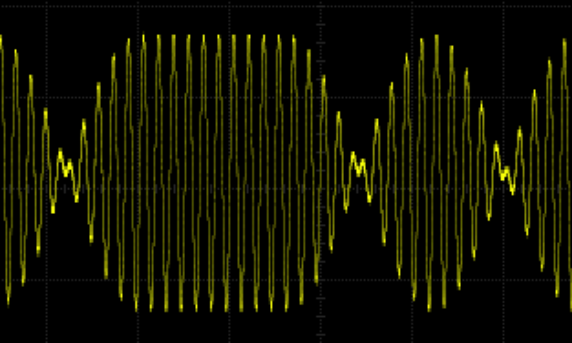
I got it to work under CubicSDR somehow, but it was not reliable. Luckily at some stage it was working (I was listening to a Classic FM broadcast) and I accidentally tapped the RSP2 and the dulcet sounds of the orchestra turned into a loud buzzing noise. I realised that it was a hardware problem and I tried to recover and nothing would work until I tried an old USB cable. The RSP2 works fine with this cable but not with any other!

Maybe I’ve lived a sheltered life but I don’t remember any device having a dodgy USB type-B socket. Micro- and mini-USB fails are common, but type-B?

Anyway, I’m happy now because I can monitor my VHF Q65 transmissions using the SDRplay.

WSJT-X and JTDX shared memory conflict

If, like me, you use a Mac and both WSJT-X and JTDX for data modes you may run into a problem I had.

The problem comes about because both applications insert a property list into /Library/LaunchDaemons. These property lists are used by the MacOS to start background processes (or daemons) at system startup. But as far as I can tell there is no defined order in which the daemons are started.

I installed the SDRplay API which as part of the install puts a property list into /Library/LaunchDaemons. This must have affected the order in which MacOS started the daemons because suddenly WSJT-X failed to start with a shared memory error. This error persisted even after a re-install and configure of WSJT-X.

I looked at /Library/LaunchDaemons because as part of the WSJT-X install you put a property list there. Sure enough, JTDX does the same (as it is derived from WSJT-X) and the property lists clash because (at least on my system and my version of JTDX) JTDX makes the shared memory size smaller than WSJT-X likes.

So, I think I was getting away with this before I installed the SDRplay API because the WSJT-X property list was being processed after the JTDX one and the shared memory was made big enough for WSJT-X. But after my SDRplay API install the JTDX property list was being processed after the WSJT-X one and the shared memory size was too small.

I fixed this situation by deleting the JTDX property list com.jtdx.sysctl as it is redundant in this circumstance.

And all is well.

SignaLink Jumpers for FT290R (correction)

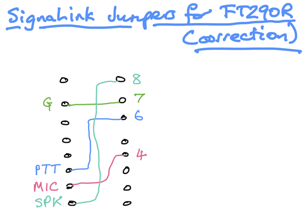
I was playing about with my FT290R and Q65 protocol and realised that I had to configure my SignaLink jumpers in a way different from how I had previously blogged. 

So these are the settings that I now find ok. Apologies if you’ve been misled by my previous post.

SignaLInk Jumpers for FT290R  correction

PIC12F1840 Si5351a VFO

To recap: this is a no-frills VFO intended as a drop-in replacement for a Colpitt’s oscillator in a Direct Conversion receiver. It allows the frequency to be changed within limits set in the code and allows the tuning to be toggled between fast and slow. An LED lights if a frequency limit is reached.

I decided what to use instead of the PICs I usually choose. The answer is: … more modern PICs! A lot of the competition are modules which makes them bigger. 

I bought a PICkit 3 which seems to be a lot cheaper than when I last looked. This allows me to program a PIC12F1840 which is much smaller than a PIC16F887. So I have ported the PIC16F887 Si5351a VFO code to that PIC. I have improved the encoder turn handling. With the encoder I’m using I needed to debounce by adding capacitors to ground. The tuning speed is toggled with a button in the encoder. It may be nicer to have a switch instead, perhaps a DIP switch for the tuning as holding down the button while tuning is a bit clumsy.
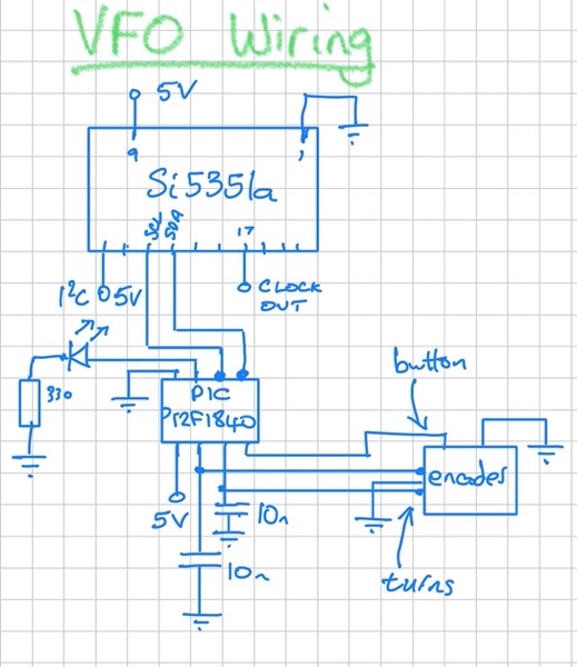
VFO Wiring

The PIC12F1840 has a sleep instruction so the code now does all the encoder turn processing in the ISR. The main loop goes to sleep and all that is done in it is to change the frequency of the Si5351a. So the PIC is asleep nearly all the time. It only wakes up when the encoder is turned. The Si5351a is always on, though, as it is generating the clock that the received RF signal is beating against.

A separate button (or DIP switch) allows the user to change the amount the frequency changes each turn. The VFO uses 30 mA when sleeping and 40 mA when the encoder is turning. I don’t know what the Colpitt’s oscillator took.

Here’s the code.

While I was debugging the code I took the following screenshot:
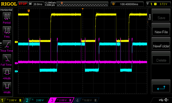
Debug Screenshot

The yellow and blue are decoder turn voltages. The pink is the LED used for debug. It goes high if the code is on the ISR. As you can see it enters the ISR at every encoder turn change. The reason I’d had to go to these lengths to see what was going on was that I’d assumed that the interrupt-on-change flag was for all changes, but it isn’t. There are separate flags for rises and falls. Moral: always read the data sheet!

The footprint of the VFO is only slightly larger than the Colpitt’s oscillator and if that used a beefier variable capacitor the new VFO would be smaller. I’m hopeful it will be useful in a lot of projects.