Adding Track Info Display (part 2)


In my previous post, I outlined some improvements I wanted to implement for the track display project using the Yamaha R-N602. This time, I’ve tackled two key enhancements: supporting non-ASCII characters and displaying the time when the receiver is off. Here’s how it came together.

Handling Non-ASCII Characters

I enjoy a wide range of music, some of which isn’t in English. This often means track titles, artist names, and album titles include characters the LCD display doesn’t render correctly. The R-N602 provides these details as UTF-8 encoded JSON but my LCD display can’t handle non-ASCII characters. Since I couldn’t find an Arduino library to convert UTF-8 to ASCII, I decided to write my own solution.

The implementation is straightforward. I created helper lambda functions to assist the processDetails function. A small map translates specific UTF-8 characters to their ASCII equivalents—for example, the character è becomes e. The map is intentionally kept short to optimize performance as it’s searched linearly. So some characters aren’t mapped.

Two lambda helpers complete the setup:

  1. One maps individual characters.
  2. The other replicates the behaviour of strncpy, applying the mapping to entire strings.

This approach allowed me to seamlessly replace strncpy calls in processDetails with my helper function. Now, a track title like Florence sur les Champs-Élysées appears as Florence sur les Champs-Elysees on the display. While this transformation sacrifices accents, it significantly improves readability—though a French speaker might disagree!

Adding a Time Display

I also added functionality to display the current time, day, and date when the R-N602 is turned off. This feature uses two Arduino pins which my LCD display shield exposes.

  • Pin A1: Toggles between GMT and BST (British Summer Time), the two time zones in Scotland. The default is GMT, but pulling the pin low switches to BST.
  • Pin A2: Controls whether the time display is always active. By default, the display shows track details, but pulling this pin low forces the clock to display.

With these additions, the project doubles as a clock.

For simplicity, the time is fetched from an NTP server since the Arduino doesn’t have a real-time clock module. Accuracy isn’t perfect—it can drift by up to 30 seconds—but it’s sufficient for this use case.

Initially, I tried using an existing Arduino library to handle the time, but I encountered issues with the day() function, which appeared unavailable probably due to a misconfiguration in my setup. Rather than spending more time troubleshooting (I’ve already dealt with my fair share of library issues), I opted to reuse some lambda functions from a previous project. Functional programming really shines here: self-contained, global-free functions are easy to repurpose with minimal effort.

Bug Fixes Along the Way

While working on these features, I also fixed a few bugs. The most significant was a scrolling issue: the last two characters of a scrolling text string weren’t displaying due to a -1 where there should have been a +1. A small fix, but it made a big difference in usability.

Wrapping Up

That’s it for now. These enhancements have made the track display project much more functional and user-friendly. If you’re interested, the updated code is available here: yamaha-song.ino.zip.

I hope this inspires some ideas for your own projects! If you’ve got questions or suggestions, feel free to share in the comments.
Adding Track Info Display to a Yamaha R-N602 with Arduino

If you’re like me, and you listen to music on a Yamaha R-N602 network receiver via Qobuz, you will  appreciate that the R-N602 can stream directly without needing a phone or tablet as an intermediary. Qobuz, with its detailed remastering, delivers the kind of sound quality that I prefer over other streaming services.

However, there’s a minor drawback: the R-N602’s display doesn’t show any track information—just a generic “Qobuz” label. I decided to fix this with a small, adaptable project using an Arduino R4 Wi-Fi and an LCD shield to display the track, artist, and album information in real-time.

Project Overview

The concept is straightforward: the Arduino connects to the same Wi-Fi as the R-N602, retrieves the currently playing track information from the receiver, and then displays it on a 2×16 LCD screen.

Here’s how it works:
1. Interfacing with the R-N602: The Yamaha receiver serves a web page in JSON format, containing details about the current track. By connecting to this page, the Arduino can extract the artist, track title, and album name.
2. Displaying the Info: The artist and album are initially shown one per line on the LCD. Then, the track name appears across both lines. If the information is longer than the screen’s width, it scrolls once to show the full text before switching to a truncated display.
3. Continuous Updates: The code loops to refresh the display periodically, keeping it in sync with the receiver’s current playback status.

Setting Up the Project

Here’s what you’ll need:
• An Arduino R4 WiFi and a compatible 2×16 LCD shield. I used these because they were to hand.

• To install some libraries needed by the project—WiFiS3, ArduinoHttpClient, ArduinoJson and LiquidCrystal.

• Access to your WiFi credentials, which are saved in a separate arduino_secrets.h file. Here’s how that file should look:

#define SECRET_SSID “Your Wifi SSID”
#define SECRET_PASS “Your Wifi Password”

Code and Demo

You can find the complete code for this project in my next post. To see it in action, check out the demo video here: IMG_2071.mp4. (BTW this video shows a scrolling bug which has been fixed.)

You’ll need to edit the code to put in your Yamaha’s IP address.

This project, while initially intended to add track info display to my setup, could be adapted for other similar use cases.

Improvements on the Horizon

There’s always room for some tweaks. Here are a few ideas I’ve been considering:
• Split track lines at a word: Ensuring clean breaks in text can make track info easier to read.
• Handle non-ASCII characters: tracks and albums often include accented characters—like “Florence sur les Champs-Élysées”—and properly supporting these would make them much more legible.
• Instant track info updates: As soon as a track changes, the displayed details should switch immediately, keeping everything in sync. This doesn’t look easy.

I’m leaning towards prioritizing non-ASCII character handling first. Many of the albums I enjoy feature accented characters, and ensuring they’re displayed correctly feels like a good improvement.

Enjoy tinkering, and happy listening!

WSPR Transmitter–Code and Development

The WSPR Transmitter has, of course, firmware code. The D1 Mini runs most of the code, with the PIC12F1640 running the LPF driver. I hold the source code in a git repository on a local server.

The D1 Mini code was developed on a Raspberry Pi 4 mostly using Arduino CLI and vi. I used a couple of helper shell scripts (ardcomp and ardup below) to compile and upload. There are a couple of libraries required: ESP8266 and HCRTC. wspr_rtc_ad9850.ino takes about 19s to compile on Raspberry Pi 4, which is about twice as fast as a Raspberry Pi 3B+. 

ardcomp: 
arduino-cli compile --fqbn esp8266:esp8266:d1_mini_clone $*
ardup: 
arduino-cli upload -p /dev/ttyUSB0 --fqbn esp8266:esp8266:d1_mini_clone $*

I used a Raspberry Pi 4 because I like to protect the USB ports on expensive computers from the possibility of smoke due to any misadventures I may cause. See my previous post.

The PIC code was developed using MPLAB on an HP14S laptop running Windows 10. The USB port is protected (hopefully) by the PICkit 3 dongle that is needed to program the PIC. I’m not a great fan of MPLAB but, once you realise you can ignore all the marketing, it suffices.

The source is in this ZIP file. It’s at the stage it was when I made smoke. The code was working–it was the power supply circuit that was faulty!

My previous posts explain the code.

WSPR Transmitter LPF Control

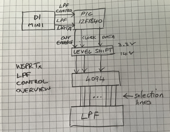
The WSPR transmitter needs an LPF to help make the transmission clean with low-level harmonics. I chose an RV3YF LPF board which has LPFs for each ham band. The band to be filtered is chosen by raising the voltage on the correct pin in a row of pins. The WSPR transmitter uses a separate PIC controller to select the correct pin. I chose a separate PIC so that the LPF and its control could perhaps be put into a module together. I haven’t actually done that but it’s possible.

WSPR Tx LPF Control Overview

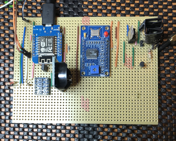
As you can see the D1 Mini tells the PIC which pin to select. The PIC uses a 4094 to convert from serial to parallel. 

I had intended that the interface between the D1 Mini and the PIC be an I2C connexion. But I couldn’t work out how to make the PIC act as an I2C slave. There are plenty of examples of I2C masters, but slaves are thin on the ground. So the interface is a home-brew protocol. Luckily I had just enough pins available on the PIC. The LPF_CONTROL line is raised by the D1 Mini when it is going to configure the LPF. It then raises and lowers the LPF_DATA line the appropriate number of times. Then the LPF_CONTROL line is lowered to denote the end of configuration. The PIC sits waiting for the LPF_CONTROL to go high and counts the number of transitions of LPF_DATA seen before LPF_CONTROL goes low.

On the output side of the PIC, my RV3YF LPF needs 14V to reliably switch the relays. So the 4094 has a 14V supply. When LPF_CONTROL goes low the PIC lowers the 4094 output enable pin. It then clocks out the number denoting the band to the 4094 thus selecting the correct LPF band. The PIC then raises the 4094 output enable pin and the band is selected on the LPF module.

I found it impossible to debug the D1/PIC interface on a breadboard as the signals were too noisy. So I decided to put the circuit straight to strip board. This solved the  debug problem and it worked happily when powered from the bench supply. I then added some circuitry to supply the 14V from an off-the-shelf buck converter. Unfortunately (or probably my own foolish fault), when I was adapting the power circuitry I managed to make (at least) the RTC module go up on smoke. I still don’t know why it did. 

I’ll post the code and the strip board layout next time.

WSPR Transmitter — Transmitting WSPR Tones

This is a follow-on from WSPR Transmitter — keeping time.

Every two minutes the transmitter code optionally transmits a message as a sequence of WSPR tones.

First the frequency to transmit on is decided—this is a round-robin though the amateur HF bands. Whether a frequency is transmitted on was decided during the initial configuration via a UART connection. The decisions were stored in EEPROM and copied to ESP8266 memory from there.

The LPF is configured to filter appropriately for this frequency. More on this is a later post.

A random offset is added to the transmit frequency to minimise collisions with other transmissions. 

The tones are then transmitted which takes most of the two minute interval. The tones to be transmitted have been compiled into the code as an array using a useful tool. Thanks Scott! The tones are for particular output power. If the output power were changed the code would need to be recompiled. The AD9850 frequency tuning word (FTW) is loaded with the frequency (RF + AF) that is to be transmitted. The code waits for the length of a tone and repeats for subsequent tones. When all the tones to be transmitted in this interval have been transmitted the AD9850 FTW is loaded with zero which stops the AD9850 from transmitting.

The AF tone part of the frequency is according to the WSPR User’s Guide Appx B: The keying rate is 12,000/8192 = 1.4648 baud. The modulation is continuous phase 4-FSK with a tone separation of 1.4648 Hz. It occupies 6 Hz. Continuous phase means the phase isn’t set to zero at the start of a symbol. 4-FSK means it uses four tones.

With an AD9850 reference clock of 125 MHz you get 125^6 / 2^32 = 0.0291 Hz resolution. For WSPR we want 1.4648 Hz or better resolution so the reference clock can be as low as 125^6 x (0.029 / 1.4648) = 2.4836 MHz. The AD9850 can cope easily with this requirement.

Next up is how the LPF band switching is carried out …

WSPR Transmitter — keeping Time

A WSPR transmission starts on an even two-minute interval. So a WSPR Transmitter needs to be able to keep track of the real time. My earlier post about setting the time on an RTC isn’t suitable for my WSPR Transmitter as the process of getting the time isn’t automatic. The best choice is between using GPS or NTP. I chose NTP as my WSPR Transmitter will always be used where there is Wi-Fi available.

Choosing NTP has some ramifications. You need to provide Wi-Fi credentials and the most convenient way for this is to ask for them once and store them somewhere. You could just store them in the code but this isn’t secure.

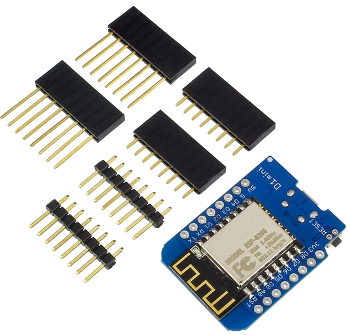
You also need to use a chip that handles Wi-Fi. I normally use PIC chips but none of the ones I had contained a Wi-Fi radio. So I looked at alternatives and chose an ESP8266 based module called a D1 Mini. This module can be programmed using the Arduino IDE via USB. It’s a little larger than most PIC chips, but is still a reasonable size.

D1 mini

A D1 mini doesn’t have any EEPROM–all of its memory is flash-based. However, there are libraries available which emulate EEPROM. So this is what I used to store the Wi-Fi credentials.

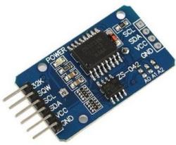
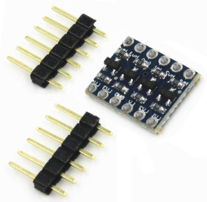
Once the NTP server has been asked for the time you need to be able to keep track of the time locally. NTP isn’t really suitable to do this by itself. So a real-time clock module or RTC is used. Previously I had used a DS1307 which seemed fine, but it wasn’t available to buy so I bought a DS3231 instead. This module is driven via an I2C bus. The D1 mini module also has I2C built-in. However the ESP8266 runs on 3.3 V and the DS3231 uses 5 V. So a level shifter is also needed.

Rtc4ch ls

The code to get the time and maintain it is lengthy but not complex and everything is sequential. When the ESP8266 starts a pin is checked to see if the Wi-Fi credentials should be asked for via the UART. If so, they are stored in the emulated EEPROM. The stored credentials are used to connect to the Wi-Fi. Then a packet is sent to the NTP server and the response is parsed to get the minutes and seconds of the current real time. None of the other time details are needed. The minutes and seconds are stored in the RTC module via the I2C bus. The time in the RTC may drift so the code occasionally retrieves the current time from the NTP server and updates the RTC. The code then loops waiting for the start of an even two-minute interval and transmits the WSPR tones. More about this in a later post. I’ll post the code then too.

Switchable LPF Response

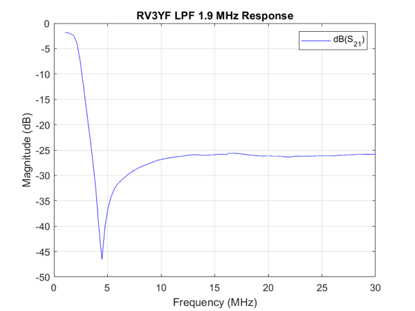
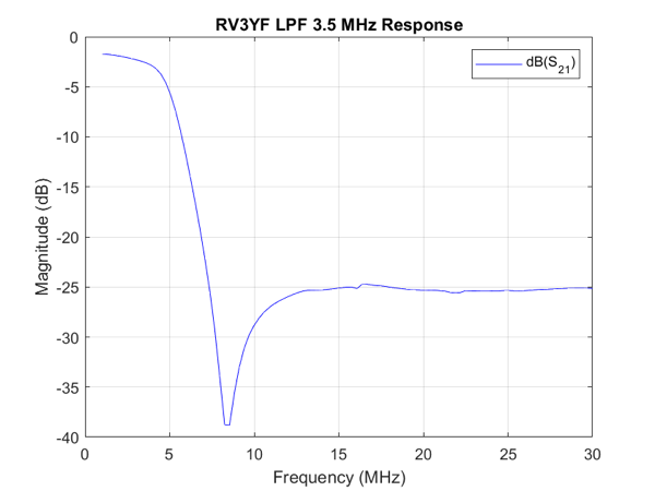
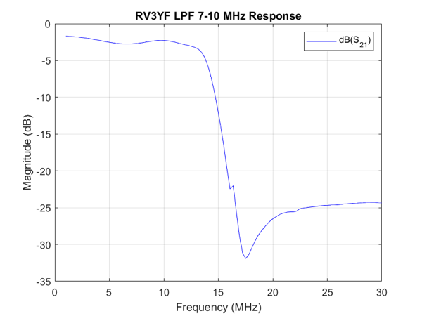
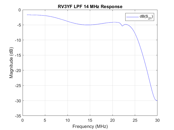
The switchable LPF for my WSPR Transmitter finally arrived and I’ve made some response graphs to test how it performs.

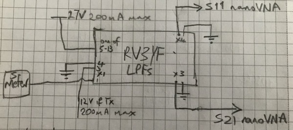
Test setup for Switchable LPF

The obvious bit of test kit to check out the LPFs is my nanoVNA. I suggest you buy a nanoVNA from a reputable dealer as there are plenty of clones which don’t work as well as the original.

The test setup is above. The 27 V in the drawing can go as low as 13.8 V, but will not work at any lower voltage. 

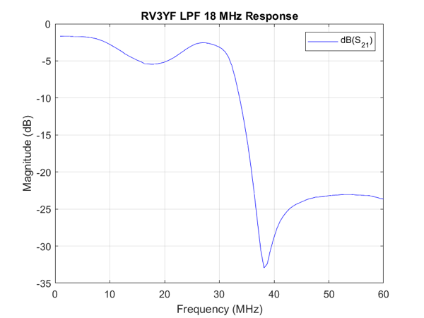
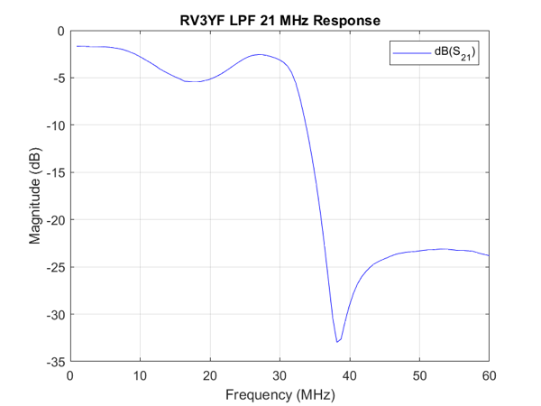
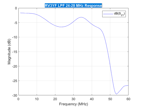
As I’ve mentioned before I find the small screen on the nanoVNA difficult to control with my clumsy hands. So I wrote another simple MATLAB script ajfLogMagS21 to drive the nanoVNA to get the response charts. The calibration done as before using my ajfCalibrate MATLAB script. The LPFs will attenuate the harmonics by 25 dB which will be enough for my feeble WSPR output.

RV3YF LPF 1 9 MHz Response

RV3YF LPF 3 5 MHz Response

RV3YF LPF 7 10 MHz Response

RV3YF LPF 14 MHz Response

RV3YF LPF 18 MHz Response


RV3YF LPF 21 MHz Response

RV3YF LPF 24 28 MHz Response

The next step is work out how to drive the switching of the bands. First thoughts are to send commands via I2C and have something convert that to a 13.8-27 V signal on the appropriate pin. I2C is attractive as I already have an I2C bus in the WSPR Transmitter.

Yet Another WSPR Transmitter

I have joined the ranks of the many who have built a WSPR Transmitter. Why? Mostly so I can have a bit of fun. The problem is difficult enough to be interesting but not so complex as to become boring. Having said that there’s a lot involved.

I can transmit WSPR with my TS590S and presumably any other off-the-shelf transceiver. But these all have fan noise so I wouldn’t want to run them overnight. So the transmitter will be able to be used to test propagation overnight.

But mostly I’ve made it to have the fun of making it.

The transmitter cycles through the amateur bands from 80m to 10m optionally transmitting on each band. An RTC module (DS3231 I2C Real Time Clock Module) is used to keep track of the real time. An AD9850 DDS Signal Generator Module produces the RF signal. Both of these are controlled by a D1 Mini ESP8266 Dev Board. The ESP8266 does all the encoding of the WSPR tones and decides when to send them. The signal from the AD9850 is run through a power amp (10W linear HF PA from QRP Labs) then through an appropriate LPF to the aerial.

WSPR Transmitter Picture

Currently I’ve only had it on air on the 40m band as I only have a home-brew 40m LPF to hand. This works fine and the signals are being picked up in Europe ok. I’m getting a switchable LPF for the other bands but it’s taking a while to arrive from Russia. However the transmitter works on every band as my TS590S close to the transmitter can pick up the stray signals when I run it into a dummy load. The signals are decoded fine using WSJT-X.

More details later.

Line-Following Robot

In an earlier part of my life I spent my working days writing device drivers for things like printer mechanisms, disc drives and so on. What they all seemed to have in common was that they turned a motor. I was missing turning motors so when I came across a book “Robot Building for Beginners” by David Cook I pricked up my ears. The book leads you from knowing nothing about electronics to building a robot which will trundle along following a line drawn on the ground. This looked like fun so I thought I’d build it.

Book Cover

The technology that the book uses to construct the robot is purely analogue. The line is detected with photoresistors and the motors are simple DC motors with no steppers in sight. What makes the book stand out is the superb way the author explains how and why electronic components work. He explains through examples about resistors and voltage dividers, through LEDs and capacitors, and from comparators to motors. Now I didn’t start from scratch with my knowledge but it seems to be a extremely good way to learn from scratch. And you get a cool robot at the end. Even if it is made from a carry-out box.

I’d built the robot and it worked but the motors were turning too fast. Slowing down a motor is harder than it sounds as all the easy options — adding resistors for example have big drawbacks. I added a PWM-based control to the motor speed controlled by pushing buttons. Here’s the PIC code: http://fletch.scot/code/line-follow.zip. This took a little while as although I had spent my time turning motors I don’t remember using PWM, so I had to learn it. I was using an online copy of the book on the learning part of the IEEE website. I went back to SkillSoft to read the next chapter of the book and the IEEE had stopped using SkillSoft and I could no longer read the book. Luckily I found a paper copy of the book for sale online and bought that so I could continue the project. But it reminded me to not rely on things in the cloud.

Here’s a video of the first run of the robot in action.

Line following robot first run 480p IMG_1145.mov

As you can see the robot needs to be made more robust. One thing I learned from making it is that my usual technique for attaching wires to pins using wires taken from ribbon cable is not good enough (despite copious application of hot glue). This leads to lots of tweaking of connectors. So before I show the robot to my grandsons I’ll have to find a better connection method or they will destroy it with their youthful exuberance.