WSJT-X and JTDX shared memory conflict

If, like me, you use a Mac and both WSJT-X and JTDX for data modes you may run into a problem I had.

The problem comes about because both applications insert a property list into /Library/LaunchDaemons. These property lists are used by the MacOS to start background processes (or daemons) at system startup. But as far as I can tell there is no defined order in which the daemons are started.

I installed the SDRplay API which as part of the install puts a property list into /Library/LaunchDaemons. This must have affected the order in which MacOS started the daemons because suddenly WSJT-X failed to start with a shared memory error. This error persisted even after a re-install and configure of WSJT-X.

I looked at /Library/LaunchDaemons because as part of the WSJT-X install you put a property list there. Sure enough, JTDX does the same (as it is derived from WSJT-X) and the property lists clash because (at least on my system and my version of JTDX) JTDX makes the shared memory size smaller than WSJT-X likes.

So, I think I was getting away with this before I installed the SDRplay API because the WSJT-X property list was being processed after the JTDX one and the shared memory was made big enough for WSJT-X. But after my SDRplay API install the JTDX property list was being processed after the WSJT-X one and the shared memory size was too small.

I fixed this situation by deleting the JTDX property list com.jtdx.sysctl as it is redundant in this circumstance.

And all is well.

SignaLink Jumpers for FT290R (correction)

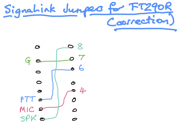
I was playing about with my FT290R and Q65 protocol and realised that I had to configure my SignaLink jumpers in a way different from how I had previously blogged. 

So these are the settings that I now find ok. Apologies if you’ve been misled by my previous post.

SignaLInk Jumpers for FT290R  correction

PIC12F1840 Si5351a VFO

To recap: this is a no-frills VFO intended as a drop-in replacement for a Colpitt’s oscillator in a Direct Conversion receiver. It allows the frequency to be changed within limits set in the code and allows the tuning to be toggled between fast and slow. An LED lights if a frequency limit is reached.

I decided what to use instead of the PICs I usually choose. The answer is: … more modern PICs! A lot of the competition are modules which makes them bigger. 

I bought a PICkit 3 which seems to be a lot cheaper than when I last looked. This allows me to program a PIC12F1840 which is much smaller than a PIC16F887. So I have ported the PIC16F887 Si5351a VFO code to that PIC. I have improved the encoder turn handling. With the encoder I’m using I needed to debounce by adding capacitors to ground. The tuning speed is toggled with a button in the encoder. It may be nicer to have a switch instead, perhaps a DIP switch for the tuning as holding down the button while tuning is a bit clumsy.

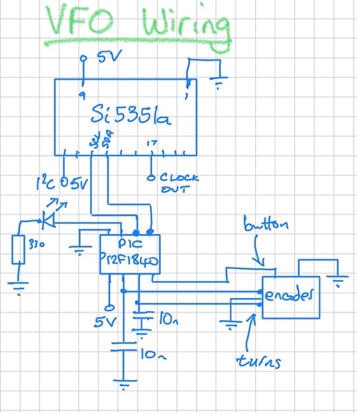
VFO Wiring

The PIC12F1840 has a sleep instruction so the code now does all the encoder turn processing in the ISR. The main loop goes to sleep and all that is done in it is to change the frequency of the Si5351a. So the PIC is asleep nearly all the time. It only wakes up when the encoder is turned. The Si5351a is always on, though, as it is generating the clock that the received RF signal is beating against.

A separate button (or DIP switch) allows the user to change the amount the frequency changes each turn. The VFO uses 30 mA when sleeping and 40 mA when the encoder is turning. I don’t know what the Colpitt’s oscillator took.

Here’s the code.

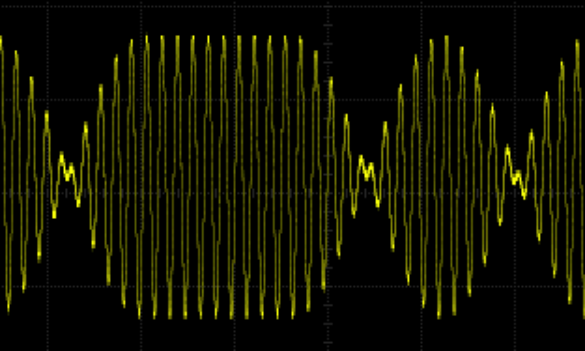
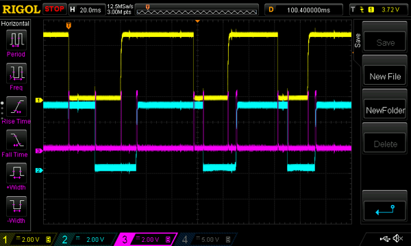
While I was debugging the code I took the following screenshot:

Debug Screenshot

The yellow and blue are decoder turn voltages. The pink is the LED used for debug. It goes high if the code is on the ISR. As you can see it enters the ISR at every encoder turn change. The reason I’d had to go to these lengths to see what was going on was that I’d assumed that the interrupt-on-change flag was for all changes, but it isn’t. There are separate flags for rises and falls. Moral: always read the data sheet!

The footprint of the VFO is only slightly larger than the Colpitt’s oscillator and if that used a beefier variable capacitor the new VFO would be smaller. I’m hopeful it will be useful in a lot of projects.

ISS SSTV Image

I finally got a decent image from the space station. The recent ISS passes have been plagued with interference from somewhere, but this image seems fine.

PD120 20210624 092404

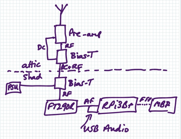
I’m using this setup — the aerial is my Cebik Moxon.

ISS 6 of 12

The Raspberry Pi 3B plus is running QSSTV. The USB Audio dongle is a 33051D. The pre-amp is an M-100.

Si5351a VFO for IC Based Receiver

This is a drop-in replacement for a Colpitt’s oscillator as the local oscillator for the mixer in a direct conversion receiver using a NE602. So it has no frills — it just generates a square wave at the required frequencies. The tuning is done with a rotary encoder. The receiver I want it for works on the CW part of the 40m band so the VFO tunes from 7.000 MHz to 7.020 MHz. An LED lights when a frequency limit has been hit. The encoder button is used to toggle the tuning rate between fast (1000 Hz per click) and slow (100 Hz per click). These can be changed to any pair of values, as can the frequency limits.

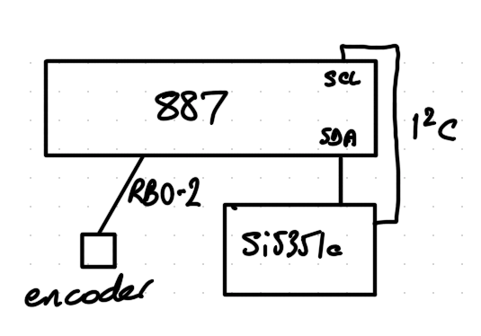
A Si5351a synthesiser is used to generate the square wave. It is controlled by a PIC micro-controller.

PIC 887 VFO Layout

I wanted to use a small 8-pin PIC for this to make the VFO have a small footprint. I chose a PIC12F1840 which has the I2C built-in needed to drive the Si5351a. But I found that I couldn’t program this PIC with my ageing PICkit2. So I tried my even more ancient K150 programmer — no joy here either. So I’ve had to use a PIC16F887 for now — even though it must be twenty times bigger. I considered bit-banging the I2C with a PIC12F683 or a PIC12F688, but it looks pretty onerous and I don’t want to spend my time chasing I2C errors. It may be the time has come to move on from PICs though I haven’t seen any alternatives that appeal yet.

The code traps encoder turns as interrupts and works out which way the encoder is turning. The debounced encoder button and frequency changes are done in the main (endless) loop. The Si5351a I2C is driven using a port of Hans Summer’s Si5351a Arduino demo. Thanks Hans! I’m also using one of Hans’ Si5351a module kits. I ‘trimmed’ the 27 MHz crystal by changing the value of SI_XTAL_FREQ in si5351a.h to 27003934 which gave the expected frequencies as seen on my ancient RACAL-DANA 9916 frequency counter.

Here are the source files and make file to build the VFO.

I haven’t tried this in the receiver yet, but it’s hopefully useful as it is.

Sometimes an encoder turn isn’t seen, but this doesn’t seem to be too obvious in use. I intend to fix that when I port the code to whatever PIC replacement I choose.

Rotary Encoder Test for PIC

I’ve been playing about making simple direct conversion receivers using an NE602 for the mixer. These receivers have some sort of input network for the signal captured by the aerial, mix that with a VFO and amplify the (possibly low pass filtered) audio output from the mixer.

The “classic” version uses a Colpitt’s oscillator for the VFO. This is an analogue oscillator that feeds back via a voltage divider made by a pair of capacitors. This works well and tunes nicely and is magical in its own way. However, the tuning is quite coarse with the variable capacitors I have, and the cost of replacement variable capacitors is getting eye-watering. They can also be quite large.

So I’m trying a replacement VFO made from an Si5351a clock generator. The Si5351a will be controlled by a PIC, being my microcontroller of choice (and available in my junk box). The tuning will be done by turning a rotary encoder. 

I had a rotary encoder of the right size in my junk box and but had no way to find out how it performs. So I wrote a small test program for a PIC16F887 which drives the rotary encoder and shows on LEDs which way the encoder was turned, whether it was turned recently and whether the button on the encoder was pressed or not. I often use a PIC16F887 for tests like this as it has many i/o pins that can be digital or analogue and can be pulled up at will. I don’t think I’ll be using it for the VFO as it is quite big (40 pins!) but I’ll be able to re-use the code amended for whichever PIC is choose.

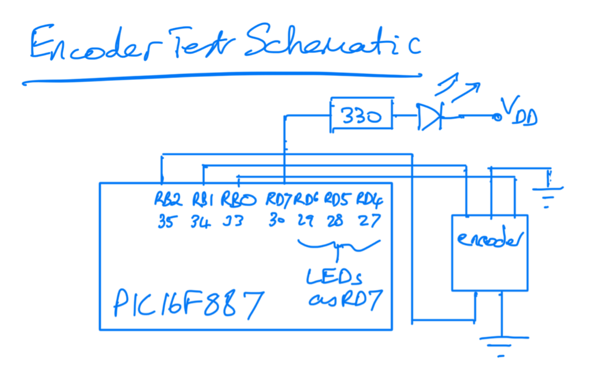
The schematic is simple: pins on the PIC PORTB are weakly pulled-up and are used for input from the encoder. Four LEDs are connected to PORTD each with a current-limiting resistor. One is the power on LED, the others show what is happening (or what the PC thinks is happening) when you play with the encoder. All the pins are digital.

Encoder Test Schematic

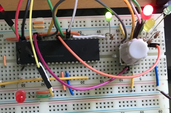
The built test is shown below. The wires you can see that are not shown in the schematic are connections to allow the programming of the PIC using a PICkit2. Ignore the LED on the bottom left as it shouldn’t be there.

Encoder Test on Breadboard

The code and make file is in this zip file. Changes made at the encoder by turning the knob are seen via interrupt. The button changes are polled. The LEDs are lit (or not) in the same polling loop.

Tune in later for the VFO itself.

Morse Sending Tutor Mock-up

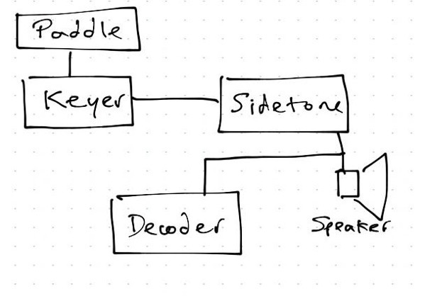
I realised that now I’ve made a CW Sidetone Oscillator, a Morse Keyer and a Morse Decoder, I could make a useful tutor for testing my sent morse.

The trick of sending good morse is in the timing. Getting the inter-character and inter-word gaps the correct length is quite difficult especially at higher speeds. So a tutor to check this could be a big help.

Morse Sending Tutor Diagram

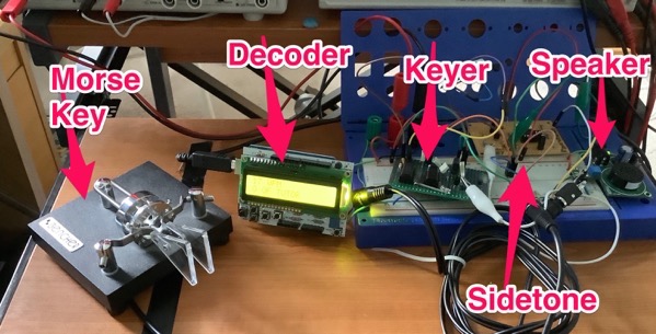
So I lashed this together using a breadboard to do the connections. 

IMG 0070

And tested it as seen in this video: Morse Tutor Demo.mov.

As you can see it’s very rough and ready. If I were to make a proper version I’d remove the WPM and tuning aid on the top line which aren’t necessary. It would fit into a small box quite easily.

It was fun to throw together!

Simple Morse Keyer

My home-brew 40m transmitter only handles a straight key at the moment, but I use a paddle. I currently use a separate keyer but this is a bit clumsy. I found a simple keyer circuit that should do the job. The keyer is by N1HFX: see http://www.rason.org/Projects/cwkeyer/cwkeyer.htm. Thanks, Mike!

The keyer is not iambic, but that’s ok for me as I usually use a single lever paddle. When I’m using a dual paddle key I don’t squeeze.

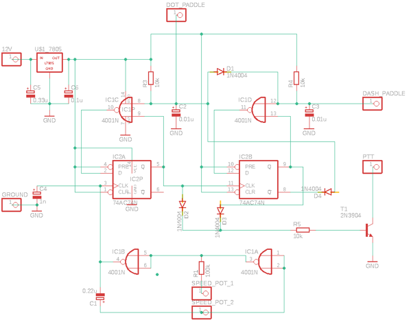
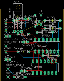
I didn’t have the exact components so I tweaked the design to cope with what I did have. Here is the new schematic and layout. I guess you shouldn’t mix IC families, but it works!

40mtx Keyer Schematic

40mtx Keyer Layout

The circuit works like this. Firstly, the oscillator. 

R2 is the variable resistor between SPEED_POT_1 and SPEED_POT_2.

Assume pins 5 and 6 are 0 V, and C1 has no charge. Pin 4 will be at 5 V.
C1 will get charged through R2 and R1. 0nce most of the 5 V is across C1, pins 1 and 2 will be at 0 V and pin 3 will change to 5 V. Pin 3 is directly connected to pins 5 and 6 so pin 4 will go to 0 V. C1 will discharge and once discharged enough pins 1 and 2 will be at 5 V and pin 3 will become 0 V which is where we came in.
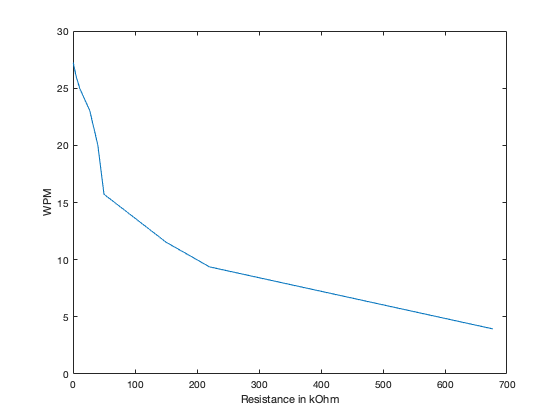
The speed of the oscillation depends on C1, R2 and R1. R2 is variable and is used to change the speed. The speed could be calculated by using the RC curve and seeing where it hits logic high and low. But I decided to do the calculations in MATLAB using these scripts. This gives a plot for R2:

Sidetone WPM

This suggests you can’t key faster than about 27 WPM. This isn’t yet a problem for me as I can barely do 17 WPM.

The keying logic is like this.  Assume the both paddles are up initially. The logic levels are like this for dots:

^ marks dot clock transition to high

                                               
CLK  N0R8     N0R9     D    Q    DOT Paddle
-    1        x        0    x    up
^    1        0        0    0    up
-    0        0        1    0    down
^    0        0        1    1    down
-    0        1        0    1    down
^    0        1        0    0    down
-    0        0        1    0    down
^    0        0        1    1    down
-    0        1        0    1    down
^    0        1        0    0    down
and so on giving equally spaced dots
-    1        1        0    0    up
^    1        0        0    0    up
and so on giving no dots.

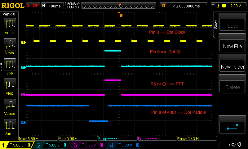
Or, less analytically: the dot paddle grounds one input to the NOR gate and the output of this is clocked into the dot flip-flop. The Q output of the flip-flop is fed back into the other NOR gate input. This gives clocked dots.

Single Dot Screenshot
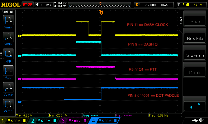
The dash flip-flop uses the Q signal from the dot flip-flop as its clock. So the dash ‘stays on’ for two dits. To make it three dits as required to make it a proper dash the ~Q from the dash flip-flop is fed to the dot paddle input making the dash have an extra dit (as ~Q will be low when Q is high thus pulling the dot paddle low).
Single Dash Screenshot

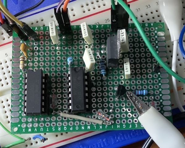
Keyer on Pad board

All this works fine. Breadboarding was fun, but I made the mistake of putting it on pad board and the soldering was onerous — there’s just too many connections between the two chips hidden under the board. Next time I’ll brush up my coding skills and use a micro-controller.

CW Sidetone Oscillator

My 40m transmitter doesn’t have any frills at all. It is CW only and so far I’ve been listening to its signal on the receiver that I’ve been using with it. This works fine as the transmitting aerial is completely separate from the receiving aerial and the transmitter power is only around one watt.

So I’ve added a sidetone oscillator to the transmitter so that I can hear what I’m sending for when I do proper transmit/receive switching with one aerial.

I looked at PIC-based and LM386-based solutions, but decided on the circuit in chapter 1 of “Experimental Methods in RF Design” by Hayward et al (EMRFD). The circuit is based on a 555 timer. It beats other circuits I looked at because it is simple to build, uses through-hole components and is plenty loud enough for my ageing ears. Although it’s a square wave oscillator it sounds fine. I may add an LPF as the harmonics are louder than the fundamental.

I didn’t have all the components specified in EMRFD so I substituted others that seem to work fine.

Here’s the circuit and layout as ‘designed’ in EAGLE.

Sidetone Board

Sidetone SchematicThe circuit works as follows. The morse key is attached to the JP1-KEY pin and when the key is keyed it grounds R2 making Q1 switch on. The 555 timer is configured as a multivibrator triggered through D1. The square wave output goes to JP2-HEADPHONE pin.

I will replace R7 with a trimmer pot as the current value makes the output too loud even for me. 

Tuning a loop with nanoVNA

One of the aerials I use is a small transmit loop. These loops have a really narrow bandwidth which is good and bad. Good in that you get much less noise, bad in that you have to keep retuning. If you stick to one frequency such as with some digital modes it is ok as you don’t have to retune too much. Other modes such as SSB and CW are less easy to use with a loop.

You can tune the loop by transmitting into it and tuning the loop until the SWR is good. This is a bit anti-social as you can be transmitting for quite some time as you tweak the tuning. I used to use a noise bridge which works quite well as long as your ears don’t get tired. The nanoVNA offers easier, more visual way of tuning. 

nanoVNA loop tuningThe nanoVNA sweep is quite slow so you need to have a fairly wide sweep span so that you can see the dip in SWR when you are tuning the loop. So you set the centre frequency and then the span and then tune until you see the dip disappearing off one end. Then you fine-tune the loop and end up with the dip at the centre frequency. The loop is now tuned as in the photo above.

This works fine with the nanoVNA GUI, but as I am nearly always running a Mac when I’m on the radio I wrote a Matlab script to do the tuning. The script is run and sets the centre frequency and span for you.

Here’s a sample tuning transcript (user input in green):

>> ajfTuneLoop
connect: Serial-/dev/tty.usbmodem4001
status:  open
press RETURN when loop is connected to ch0
Frequency to tune to (MHz) ? 7.074
tune loop for dip at the marker, press RETURN when tuned ok
close
>> 

The script is ajfTuneLoop.m.