The trick of sending good morse is in the timing. Getting the inter-character and inter-word gaps the correct length is quite difficult especially at higher speeds. So a tutor to check this could be a big help.
So I lashed this together using a breadboard to do the connections.
As you can see it’s very rough and ready. If I were to make a proper version I’d remove the WPM and tuning aid on the top line which aren’t necessary. It would fit into a small box quite easily.
My home-brew 40m transmitter only handles a straight key at the moment, but I use a paddle. I currently use a separate keyer but this is a bit clumsy. I found a simple keyer circuit that should do the job. The keyer is by N1HFX: see http://www.rason.org/Projects/cwkeyer/cwkeyer.htm. Thanks, Mike!
The keyer is not iambic, but that’s ok for me as I usually use a single lever paddle. When I’m using a dual paddle key I don’t squeeze.
I didn’t have the exact components so I tweaked the design to cope with what I did have. Here is the new schematic and layout. I guess you shouldn’t mix IC families, but it works!
The circuit works like this. Firstly, the oscillator.
R2 is the variable resistor between SPEED_POT_1 and SPEED_POT_2.
Assume pins 5 and 6 are 0 V, and C1 has no charge. Pin 4 will be at 5 V. C1 will get charged through R2 and R1. 0nce most of the 5 V is across C1, pins 1 and 2 will be at 0 V and pin 3 will change to 5 V. Pin 3 is directly connected to pins 5 and 6 so pin 4 will go to 0 V. C1 will discharge and once discharged enough pins 1 and 2 will be at 5 V and pin 3 will become 0 V which is where we came in. The speed of the oscillation depends on C1, R2 and R1. R2 is variable and is used to change the speed. The speed could be calculated by using the RC curve and seeing where it hits logic high and low. But I decided to do the calculations in MATLAB using these scripts. This gives a plot for R2:
This suggests you can’t key faster than about 27 WPM. This isn’t yet a problem for me as I can barely do 17 WPM.
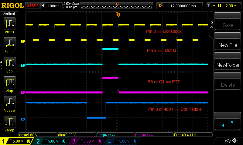
The keying logic is like this. Assume the both paddles are up initially. The logic levels are like this for dots:
^ marks dot clock transition to high
CLK  N0R8     N0R9     D    Q    DOT Paddle
-    1        x        0    x    up
^    1        0        0    0    up
-    0        0        1    0    down
^    0        0        1    1    down
-    0        1        0    1    down
^    0        1        0    0    down
-    0        0        1    0    down
^    0        0        1    1    down
-    0        1        0    1    down
^    0        1        0    0    down
and so on giving equally spaced dots
-    1        1        0    0    up
^    1        0        0    0    up
and so on giving no dots.
Or, less analytically: the dot paddle grounds one input to the NOR gate and the output of this is clocked into the dot flip-flop. The Q output of the flip-flop is fed back into the other NOR gate input. This gives clocked dots.
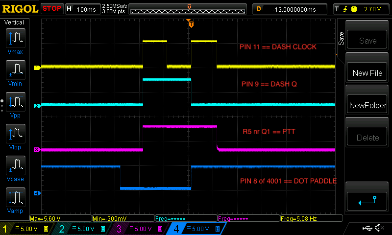
Single Dot ScreenshotThe dash flip-flop uses the Q signal from the dot flip-flop as its clock. So the dash ‘stays on’ for two dits. To make it three dits as required to make it a proper dash the ~Q from the dash flip-flop is fed to the dot paddle input making the dash have an extra dit (as ~Q will be low when Q is high thus pulling the dot paddle low).Single Dash Screenshot
All this works fine. Breadboarding was fun, but I made the mistake of putting it on pad board and the soldering was onerous — there’s just too many connections between the two chips hidden under the board. Next time I’ll brush up my coding skills and use a micro-controller.
My 40m transmitter doesn’t have any frills at all. It is CW only and so far I’ve been listening to its signal on the receiver that I’ve been using with it. This works fine as the transmitting aerial is completely separate from the receiving aerial and the transmitter power is only around one watt.
So I’ve added a sidetone oscillator to the transmitter so that I can hear what I’m sending for when I do proper transmit/receive switching with one aerial.
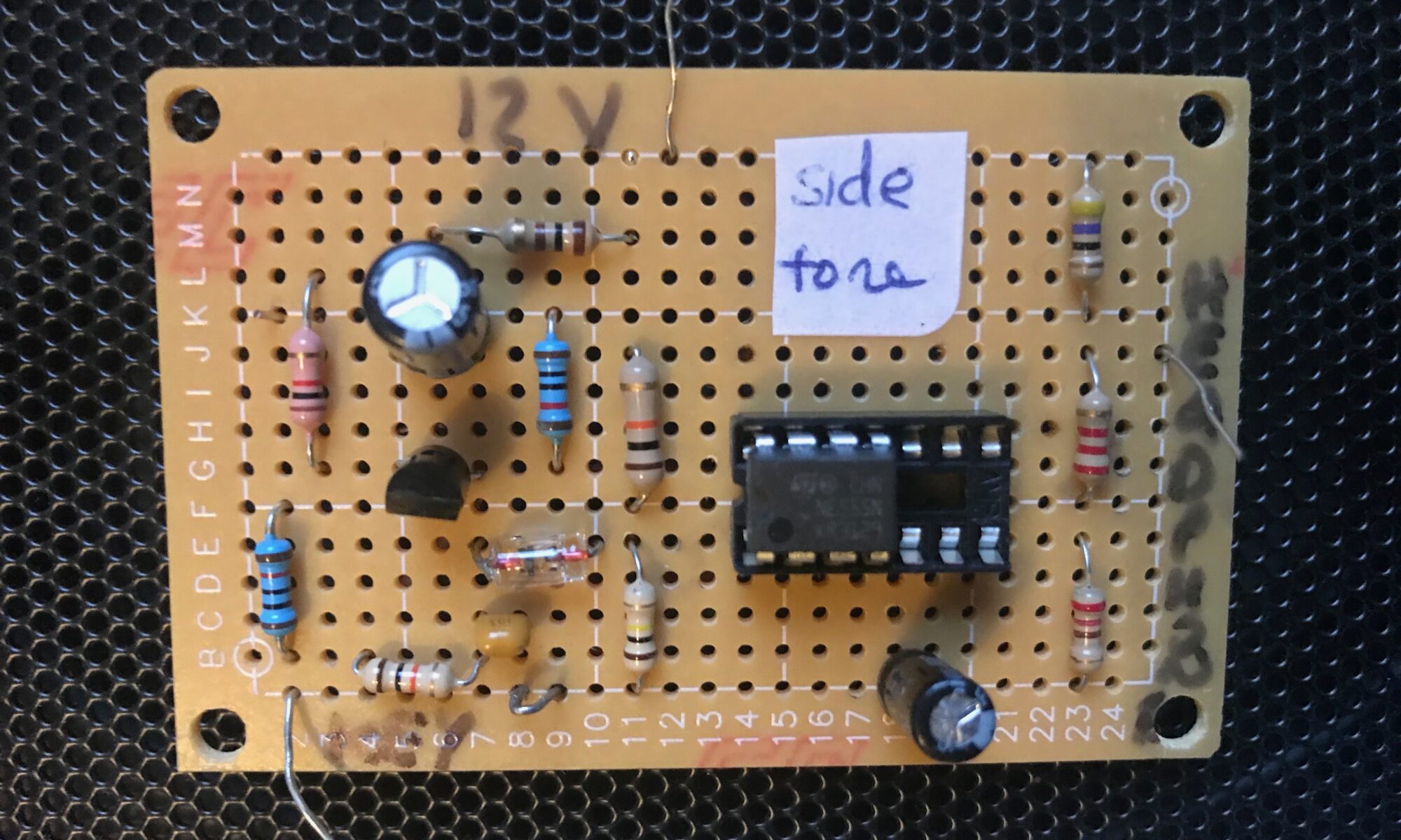
I looked at PIC-based and LM386-based solutions, but decided on the circuit in chapter 1 of “Experimental Methods in RF Design” by Hayward et al (EMRFD). The circuit is based on a 555 timer. It beats other circuits I looked at because it is simple to build, uses through-hole components and is plenty loud enough for my ageing ears. Although it’s a square wave oscillator it sounds fine. I may add an LPF as the harmonics are louder than the fundamental.
I didn’t have all the components specified in EMRFD so I substituted others that seem to work fine.
Here’s the circuit and layout as ‘designed’ in EAGLE.
The circuit works as follows. The morse key is attached to the JP1-KEY pin and when the key is keyed it grounds R2 making Q1 switch on. The 555 timer is configured as a multivibrator triggered through D1. The square wave output goes to JP2-HEADPHONE pin.
I will replace R7 with a trimmer pot as the current value makes the output too loud even for me.


 The circuit works as follows. The morse key is attached to the JP1-KEY pin and when the key is keyed it grounds R2 making Q1 switch on. The 555 timer is configured as a multivibrator triggered through D1. The square wave output goes to JP2-HEADPHONE pin.