WSPR Transmitter — Transmitting WSPR Tones

This is a follow-on from WSPR Transmitter — keeping time.

Every two minutes the transmitter code optionally transmits a message as a sequence of WSPR tones.

First the frequency to transmit on is decided—this is a round-robin though the amateur HF bands. Whether a frequency is transmitted on was decided during the initial configuration via a UART connection. The decisions were stored in EEPROM and copied to ESP8266 memory from there.

The LPF is configured to filter appropriately for this frequency. More on this is a later post.

A random offset is added to the transmit frequency to minimise collisions with other transmissions. 

The tones are then transmitted which takes most of the two minute interval. The tones to be transmitted have been compiled into the code as an array using a useful tool. Thanks Scott! The tones are for particular output power. If the output power were changed the code would need to be recompiled. The AD9850 frequency tuning word (FTW) is loaded with the frequency (RF + AF) that is to be transmitted. The code waits for the length of a tone and repeats for subsequent tones. When all the tones to be transmitted in this interval have been transmitted the AD9850 FTW is loaded with zero which stops the AD9850 from transmitting.

The AF tone part of the frequency is according to the WSPR User’s Guide Appx B: The keying rate is 12,000/8192 = 1.4648 baud. The modulation is continuous phase 4-FSK with a tone separation of 1.4648 Hz. It occupies 6 Hz. Continuous phase means the phase isn’t set to zero at the start of a symbol. 4-FSK means it uses four tones.

With an AD9850 reference clock of 125 MHz you get 125^6 / 2^32 = 0.0291 Hz resolution. For WSPR we want 1.4648 Hz or better resolution so the reference clock can be as low as 125^6 x (0.029 / 1.4648) = 2.4836 MHz. The AD9850 can cope easily with this requirement.

Next up is how the LPF band switching is carried out …

Rotary Encoder Test for PIC

I’ve been playing about making simple direct conversion receivers using an NE602 for the mixer. These receivers have some sort of input network for the signal captured by the aerial, mix that with a VFO and amplify the (possibly low pass filtered) audio output from the mixer.

The “classic” version uses a Colpitt’s oscillator for the VFO. This is an analogue oscillator that feeds back via a voltage divider made by a pair of capacitors. This works well and tunes nicely and is magical in its own way. However, the tuning is quite coarse with the variable capacitors I have, and the cost of replacement variable capacitors is getting eye-watering. They can also be quite large.

So I’m trying a replacement VFO made from an Si5351a clock generator. The Si5351a will be controlled by a PIC, being my microcontroller of choice (and available in my junk box). The tuning will be done by turning a rotary encoder. 

I had a rotary encoder of the right size in my junk box and but had no way to find out how it performs. So I wrote a small test program for a PIC16F887 which drives the rotary encoder and shows on LEDs which way the encoder was turned, whether it was turned recently and whether the button on the encoder was pressed or not. I often use a PIC16F887 for tests like this as it has many i/o pins that can be digital or analogue and can be pulled up at will. I don’t think I’ll be using it for the VFO as it is quite big (40 pins!) but I’ll be able to re-use the code amended for whichever PIC is choose.

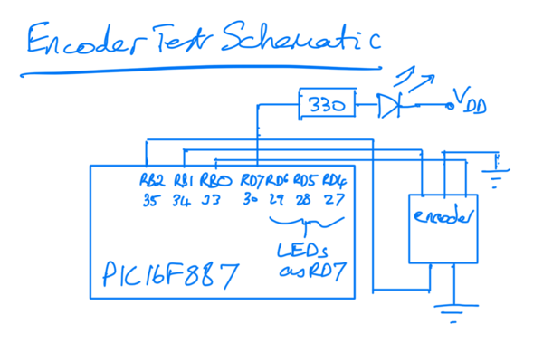
The schematic is simple: pins on the PIC PORTB are weakly pulled-up and are used for input from the encoder. Four LEDs are connected to PORTD each with a current-limiting resistor. One is the power on LED, the others show what is happening (or what the PC thinks is happening) when you play with the encoder. All the pins are digital.

Encoder Test Schematic

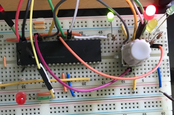
The built test is shown below. The wires you can see that are not shown in the schematic are connections to allow the programming of the PIC using a PICkit2. Ignore the LED on the bottom left as it shouldn’t be there.

Encoder Test on Breadboard

The code and make file is in this zip file. Changes made at the encoder by turning the knob are seen via interrupt. The button changes are polled. The LEDs are lit (or not) in the same polling loop.

Tune in later for the VFO itself.

50 Hz strobe

Some of my friends were in a band ’The Valves’ in the late 70s and more recently they have been playing the occasional (and excellent) gig here in Edinburgh. This year they brought out their first album — on vinyl. It’s called ‘Better Late …’. You can find all about them on Facebook: search for ‘The Mighty Valves’. 

Now I was supposed to be getting copy of the album at mates’ rates. But that involved meeting one of them which is not possible during COVID lockdown here on Scotland. But to prepare for its eagerly awaited arrival I thought I’d better dust off my turntable. I had ripped all my albums to MP3 ages ago and rarely used it. I found that it only worked at 45 rpm. The cure was to spray switch cleaner at the 33/45 rpm switch which was hidden inside — the switch that you press was pressing a plastic piece at right angles to the actual switch. 

I though I might as well check it was still at the correct speed and remembered I had a strobe ‘disc’. It’s actually a piece of paper from vinylengine.com.
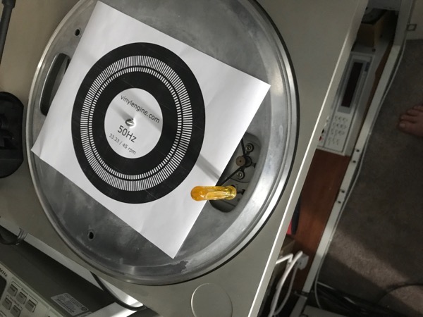
Stobe disc on turntable

The idea of the strobe disc is that the lines on the concentric circles will normally be blurred when the disc is spinning. When you shine a light strobing at 50 Hz the lines freeze and appear to be still if the disc is turning at 33 rpm. If the disc is spinning at some other speed the lines may look like they are spinning slowly backwards or forwards. I tried to take some videos of this working but they don’t show properly presumably due to the frame rate of the camera.

So how to get a 50 Hz light in these days without incandescent bulbs? Here’s a quick program for an Arduino which toggles a digital output at 50 Hz. A white LED and a 330 ohm resistor in series to ground is the entire circuit. About as simple as it gets.

/*
strobe LED at 50 Hz
*/
int ledPin = 12;

// the setup function runs once when you press reset or power the board
void setup() {
pinMode(ledPin, OUTPUT);
}

// the loop function runs over and over again forever
void loop() {
int delayms = 20/2; // 50 Hz has a period of 1/50 seconds = 20 ms
delay(delayms);
digitalWrite(ledPin, HIGH);
delay(delayms);
digitalWrite(ledPin, LOW);
}

I compiled this for an Arduino DUE which I had to hand, though I imagine it would work fine on an UNO. The ledPin value may need changed though. I compiled it using Arduino-cli with this incantation:

arduino-cli compile -b arduino:sam:arduino_due_x_dbg -p /dev/cu.usbmodem141101 -u
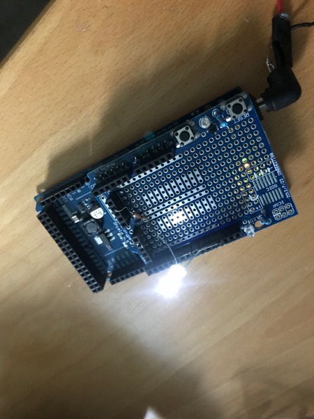
Arduino with shield

That meant I didn’t need to use the Arduino IDE and could use my code editor of choice (vim). Arduino-cli works well — thanks to the developers! BTW the Arduino IDE is fine, I’m just a terminal junkie. An oscilloscope confirmed the signal was at 50 Hz.

The picture shows me using a prototype shield on top of the Arduino. The shield is not necessary but the reset switch is easier to get at with the shield so I used it.

Did it work? Well… My turntable is a Pioneer PL-120 and the designers decided to make the speed control impossible to use while the turntable is spinning. See the yellow screwdriver which is at the speed control adjust screw in the picture of the strobe ‘disc’. So my fond dreams of shining the strobe at the disc and simultaneously adjusting the speed were dashed. I found it really difficult to do. Also it is summer here in Scotland and the weather has been good so the sun is in the sky nearly all of the time I am awake. So the LED could have been brighter to compete with the sun. It would work fine in winter or if I had better curtains.

In the end I put on a record and counted how long 10 revolutions took and did the arithmetic. Adjusted the speed (did I tell you the screwdriver is difficult to align with the speed control slot?) And repeated until good. So I didn’t actually use the strobe in the end.

A final test: ‘Oh! Wot A Dream’ by Kevin Ayers is billed as taking 2m 47s and I timed it at about 2m 46s. That’s good enough for rock and roll. Maybe someone with perfect pitch would howl in frustration — as am I waiting for the ‘Better Late…’ album.
Bit Banging on PIC12F683

The PIC12F683 Microcontroller comes in a useful 8 pin DIL package. I favour this over smaller devices as it allows my ageing eyes to cope with connecting it to the rest of the circuit.

However, this PIC does not come with a UART and so any text debug needs to be output using ‘bit-banging’. I needed to debug a PWM motor drive so I tried to find an existing implementation of bit-banging on this or similar PICs developed in C but couldn’t find any. So here’s my solution.

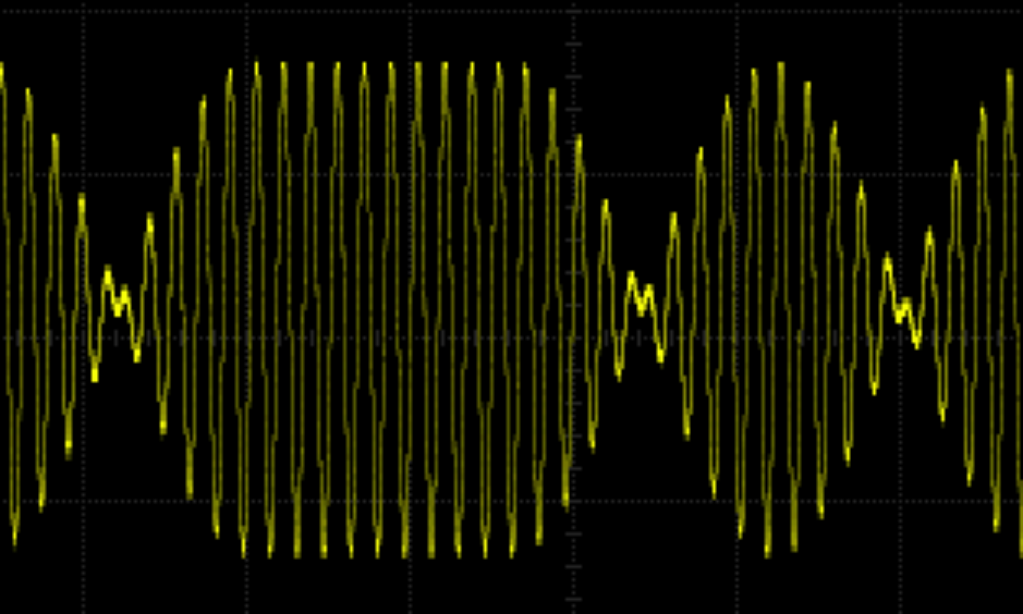
This code allows communication at 9600 baud only. This is a reasonable speed for text debug as it allows fairly rapid output but won’t be too fast for any modern computer. The output is digital high and low on the GP0 pin. So highs will be at the supply voltage (Vdd) and lows will be at 0V. For this PIC Vdd is from 2 to 5.5V. I did all my testing with a 5V supply. The communication is 8-bit, no parity and one stop bit (8N1 for short). The remote UART used in testing was a Dangerous Prototypes’ Bus Pirate. The text was displayed on a Mac mini terminal using GNU screen: screen /dev/tty.usbserial-A9048DB4 115200,cs8,-parenb,-cstopb,-hupcl.

The code uses timer 1 as a counter to work out how long to keep the signal high or low. This means the timing of the code you are debugging will be way off as the code does a lot of looping to check the counter registers. But if the code being debugged is timing critical you shouldn’t be using text debug anyway. In that case you are better off simulating, flashing LEDs or looking at signals with a ‘scope or logic analyser.

The meat of the bit-banging code is in the putcharGP0 function. This sets or resets the GP0 port depending on the value of the bit to be transmitted. After each set or reset the code loops waiting for 1/9600 = 104µs. This loop is in the ‘WAIT_SYMBOL_TIME’ macro. This macro takes an argument which allows the loop to be adjusted allowing for the time taken to run the code between each bit. The macro is called ‘WAIT_SYMBOL_TIME’ as in this case each symbol is a single bit. Each character has a start bit, 8 data bits and a single stop bit. 

The code is built using this make file which uses Microchip’s xc8 C compiler and programs the PIC using a PICkit2.