ISS SSTV Image

I finally got a decent image from the space station. The recent ISS passes have been plagued with interference from somewhere, but this image seems fine.

PD120 20210624 092404

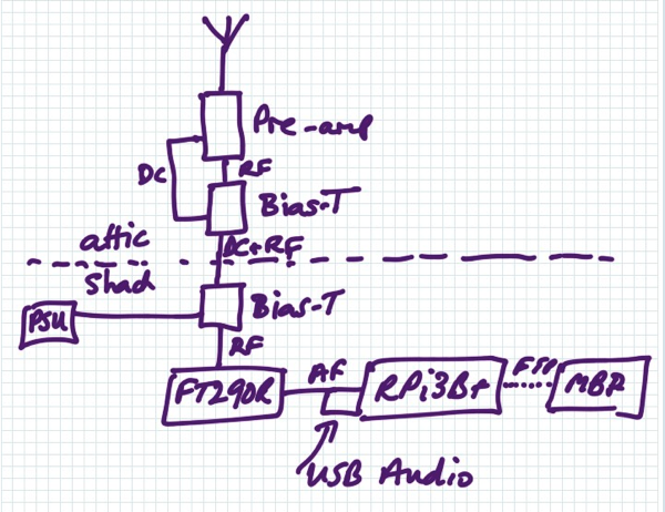
I’m using this setup — the aerial is my Cebik Moxon.

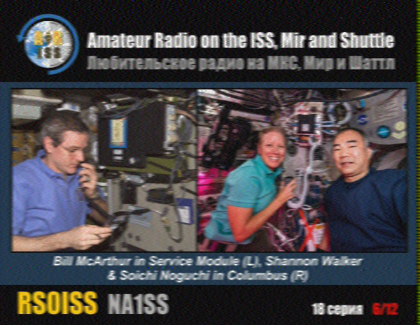
ISS 6 of 12

The Raspberry Pi 3B plus is running QSSTV. The USB Audio dongle is a 33051D. The pre-amp is an M-100.

Si5351a VFO for IC Based Receiver

This is a drop-in replacement for a Colpitt’s oscillator as the local oscillator for the mixer in a direct conversion receiver using a NE602. So it has no frills — it just generates a square wave at the required frequencies. The tuning is done with a rotary encoder. The receiver I want it for works on the CW part of the 40m band so the VFO tunes from 7.000 MHz to 7.020 MHz. An LED lights when a frequency limit has been hit. The encoder button is used to toggle the tuning rate between fast (1000 Hz per click) and slow (100 Hz per click). These can be changed to any pair of values, as can the frequency limits.

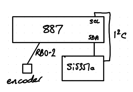
A Si5351a synthesiser is used to generate the square wave. It is controlled by a PIC micro-controller.

PIC 887 VFO Layout

I wanted to use a small 8-pin PIC for this to make the VFO have a small footprint. I chose a PIC12F1840 which has the I2C built-in needed to drive the Si5351a. But I found that I couldn’t program this PIC with my ageing PICkit2. So I tried my even more ancient K150 programmer — no joy here either. So I’ve had to use a PIC16F887 for now — even though it must be twenty times bigger. I considered bit-banging the I2C with a PIC12F683 or a PIC12F688, but it looks pretty onerous and I don’t want to spend my time chasing I2C errors. It may be the time has come to move on from PICs though I haven’t seen any alternatives that appeal yet.

The code traps encoder turns as interrupts and works out which way the encoder is turning. The debounced encoder button and frequency changes are done in the main (endless) loop. The Si5351a I2C is driven using a port of Hans Summer’s Si5351a Arduino demo. Thanks Hans! I’m also using one of Hans’ Si5351a module kits. I ‘trimmed’ the 27 MHz crystal by changing the value of SI_XTAL_FREQ in si5351a.h to 27003934 which gave the expected frequencies as seen on my ancient RACAL-DANA 9916 frequency counter.

Here are the source files and make file to build the VFO.

I haven’t tried this in the receiver yet, but it’s hopefully useful as it is.

Sometimes an encoder turn isn’t seen, but this doesn’t seem to be too obvious in use. I intend to fix that when I port the code to whatever PIC replacement I choose.

Rotary Encoder Test for PIC

I’ve been playing about making simple direct conversion receivers using an NE602 for the mixer. These receivers have some sort of input network for the signal captured by the aerial, mix that with a VFO and amplify the (possibly low pass filtered) audio output from the mixer.

The “classic” version uses a Colpitt’s oscillator for the VFO. This is an analogue oscillator that feeds back via a voltage divider made by a pair of capacitors. This works well and tunes nicely and is magical in its own way. However, the tuning is quite coarse with the variable capacitors I have, and the cost of replacement variable capacitors is getting eye-watering. They can also be quite large.

So I’m trying a replacement VFO made from an Si5351a clock generator. The Si5351a will be controlled by a PIC, being my microcontroller of choice (and available in my junk box). The tuning will be done by turning a rotary encoder. 

I had a rotary encoder of the right size in my junk box and but had no way to find out how it performs. So I wrote a small test program for a PIC16F887 which drives the rotary encoder and shows on LEDs which way the encoder was turned, whether it was turned recently and whether the button on the encoder was pressed or not. I often use a PIC16F887 for tests like this as it has many i/o pins that can be digital or analogue and can be pulled up at will. I don’t think I’ll be using it for the VFO as it is quite big (40 pins!) but I’ll be able to re-use the code amended for whichever PIC is choose.

The schematic is simple: pins on the PIC PORTB are weakly pulled-up and are used for input from the encoder. Four LEDs are connected to PORTD each with a current-limiting resistor. One is the power on LED, the others show what is happening (or what the PC thinks is happening) when you play with the encoder. All the pins are digital.
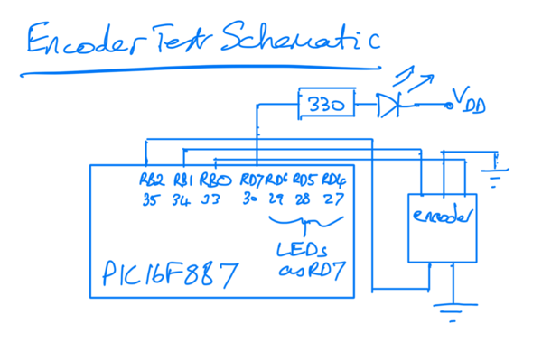
Encoder Test Schematic

The built test is shown below. The wires you can see that are not shown in the schematic are connections to allow the programming of the PIC using a PICkit2. Ignore the LED on the bottom left as it shouldn’t be there.
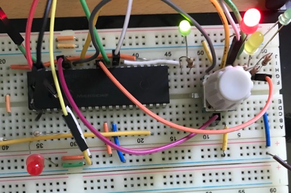
Encoder Test on Breadboard

The code and make file is in this zip file. Changes made at the encoder by turning the knob are seen via interrupt. The button changes are polled. The LEDs are lit (or not) in the same polling loop.

Tune in later for the VFO itself.