I’ve been playing about making simple direct conversion receivers using an NE602 for the mixer. These receivers have some sort of input network for the signal captured by the aerial, mix that with a VFO and amplify the (possibly low pass filtered) audio output from the mixer.
The “classic” version uses a Colpitt’s oscillator for the VFO. This is an analogue oscillator that feeds back via a voltage divider made by a pair of capacitors. This works well and tunes nicely and is magical in its own way. However, the tuning is quite coarse with the variable capacitors I have, and the cost of replacement variable capacitors is getting eye-watering. They can also be quite large.
So I’m trying a replacement VFO made from an Si5351a clock generator. The Si5351a will be controlled by a PIC, being my microcontroller of choice (and available in my junk box). The tuning will be done by turning a rotary encoder.
I had a rotary encoder of the right size in my junk box and but had no way to find out how it performs. So I wrote a small test program for a PIC16F887 which drives the rotary encoder and shows on LEDs which way the encoder was turned, whether it was turned recently and whether the button on the encoder was pressed or not. I often use a PIC16F887 for tests like this as it has many i/o pins that can be digital or analogue and can be pulled up at will. I don’t think I’ll be using it for the VFO as it is quite big (40 pins!) but I’ll be able to re-use the code amended for whichever PIC is choose.
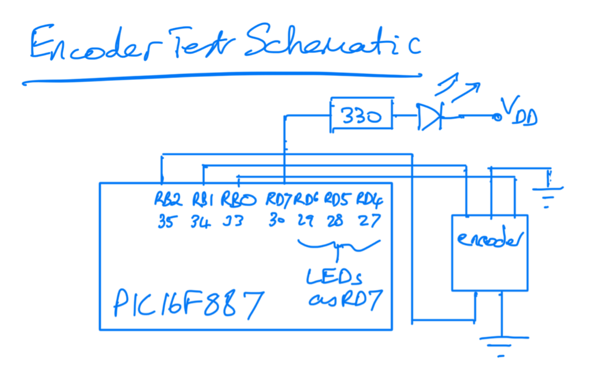
The schematic is simple: pins on the PIC PORTB are weakly pulled-up and are used for input from the encoder. Four LEDs are connected to PORTD each with a current-limiting resistor. One is the power on LED, the others show what is happening (or what the PC thinks is happening) when you play with the encoder. All the pins are digital.

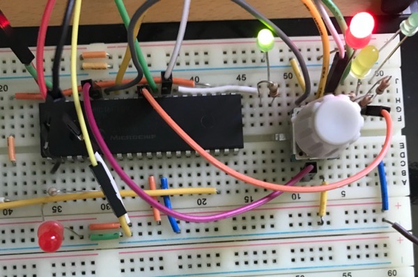
The built test is shown below. The wires you can see that are not shown in the schematic are connections to allow the programming of the PIC using a PICkit2. Ignore the LED on the bottom left as it shouldn’t be there.

The code and make file is in this zip file. Changes made at the encoder by turning the knob are seen via interrupt. The button changes are polled. The LEDs are lit (or not) in the same polling loop.
Tune in later for the VFO itself.
