40m Low Pass Filter
This LPF was intended for use with my 40m Tx. I wanted it to:
- Pass RF at 40m frequencies with less than 0.2dB insertion loss
- Reduce harmonics of 40m transmitter by at least 75dBc
- Be self-contained
- Be passive
- Handle RF power up to 10W
- Be resistant to RFI
- Causes no RFI
- Fundamental frequency input waveform faithfully produced at output
- Use standard capacitor values
- Have BNC input and output
Design
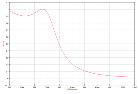
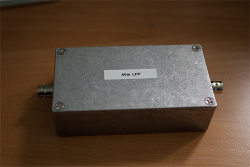
The LPF design was taken from EMRFD (Hayward et al. 2009) section 1.13. It is a 7th-order Chebyshev design with a 7.5MHz ripple cutoff frequency and a ripple of 0.07 dB. The LPF is enclosed in a die-cast aluminium box with BNC sockets for input and output. This should make it meet the RFI requirement.
The LPF was modelled using QUCS. A simulated sweep from 6MHz to 11 MHz is shown. Frequencies over 11 MHz had zero or very low amplitudes.
Here is the frequency response: 
Here is the schematic used to produce the QUCS frequency response:

Implementation
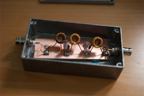
The capacitors are a mixture of polythene and ceramic disc as these were the types available in the shack. The designed inductors are T50–6 toroids with 19 turns and 21 turns respectively. In each case the number of turns needed to be reduced by one and the turns spread out to get reasonably close values to the design. So the actual turns used were 18 and 20. Size 22 SWG enamelled wire was used. The inductances were measured (out of circuit) using a home-brewed inductance tester (see ARRL Handbook (Silver 2012) section 25.8.3). The measured inductances were \(L1=1.508 \mu H, L2=1.73 \mu H\), and \(L3=1.536 \mu H\). Modelling these actual values with QUCS shows a very similar curve to the one with the design values. The components were placed ‘ugly’ style on a ground plane made from copperclad board, with islands to connect non-grounded nodes using MeSquares. The input and output ports are BNC sockets bolted to the die-cast box.


Testing
Testing Approach
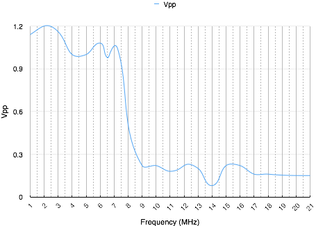
The assembled LPF was terminated with a \(50 \Omega\) load. It was then injected with sine waves at different frequencies at \(1V_{p-p}\) from my AimTTI TG120 function generator. My Rigol DS1104Z oscilloscope was used to measure the resulting peak-to-peak voltages. Here are the results:

The 3dB cut-off is at about 8MHz.
The examination of the FFT for a 7MHz square wave shows the amplitude at 14MHz (the 2nd harmonic) is at –55dBc or lower (in the noise), at 21MHz (the 3rd harmonic) is at –39dBc, at 28MHz (the 4th harmonic) is at –55dBc or lower (in the noise), and at 35MHz (the 5th harmonic) is at –39dBc. The 40m transmitter outputs 14MHz at –38dBc, and 21 MHz at –39.6dBc, so with the LPF the overall attenuation is 93dB for 14MHz and 78dB for 21 MHz. This seems fine.
The LPF was then used outbound from the 40m transmitter at a fixed frequency of 7.027 MHz, again into a \(50 \Omega\) dummy load. The peak-to-peak voltages at the input and output of the LPF were measured. The output waveform had the same shape as the input.
The LPF was then injected with a 7MHz square wave at \(1V_{p-p}\) and the amplitudes of the harmonics were examined using FFT on the DS1104Z scope. The LPF was terminated with \(50 \Omega\) loads at each end.
A homebrew RF sniffer was used to measure RFI from the LPF. No RFI was detected. I didn’t do any specific tests on the LPF’s response to RFI as it seemed low risk and the testing would be onerous.
The test for handling 10W was not possible with the TG120 function generator as it does not have enough power, but it can output 19.8V at 9MHz which is 7.84W without getting too warm. I ran a test at 7.84W anyway and the input and output waveforms were the same shape. The temperature of the components in the LPF rose by \(1^{\circ} C\) after 5 minutes, in an ambient temperature of \(21^{\circ} C\).
Conclusions
The LPF functions adequately despite the issues below.
Issues
- I’m not sure what sort of capacitors should be used.
- All inductors had to have their turns reduced. Perhaps the way I’m counting the turns is incorrect.
- The attenuated voltages do not drop to zero. It is unclear if this is a testing fault or not.