WSPR Transmitter–Code and Development

The WSPR Transmitter has, of course, firmware code. The D1 Mini runs most of the code, with the PIC12F1640 running the LPF driver. I hold the source code in a git repository on a local server.

The D1 Mini code was developed on a Raspberry Pi 4 mostly using Arduino CLI and vi. I used a couple of helper shell scripts (ardcomp and ardup below) to compile and upload. There are a couple of libraries required: ESP8266 and HCRTC. wspr_rtc_ad9850.ino takes about 19s to compile on Raspberry Pi 4, which is about twice as fast as a Raspberry Pi 3B+. 

ardcomp: 
arduino-cli compile --fqbn esp8266:esp8266:d1_mini_clone $*
ardup: 
arduino-cli upload -p /dev/ttyUSB0 --fqbn esp8266:esp8266:d1_mini_clone $*

I used a Raspberry Pi 4 because I like to protect the USB ports on expensive computers from the possibility of smoke due to any misadventures I may cause. See my previous post.

The PIC code was developed using MPLAB on an HP14S laptop running Windows 10. The USB port is protected (hopefully) by the PICkit 3 dongle that is needed to program the PIC. I’m not a great fan of MPLAB but, once you realise you can ignore all the marketing, it suffices.

The source is in this ZIP file. It’s at the stage it was when I made smoke. The code was working–it was the power supply circuit that was faulty!

My previous posts explain the code.
WSPR Transmitter LPF Control

The WSPR transmitter needs an LPF to help make the transmission clean with low-level harmonics. I chose an RV3YF LPF board which has LPFs for each ham band. The band to be filtered is chosen by raising the voltage on the correct pin in a row of pins. The WSPR transmitter uses a separate PIC controller to select the correct pin. I chose a separate PIC so that the LPF and its control could perhaps be put into a module together. I haven’t actually done that but it’s possible.

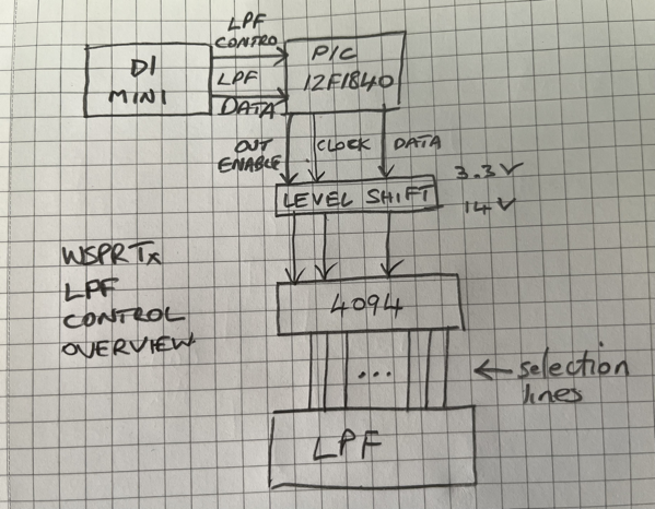
WSPR Tx LPF Control Overview

As you can see the D1 Mini tells the PIC which pin to select. The PIC uses a 4094 to convert from serial to parallel. 

I had intended that the interface between the D1 Mini and the PIC be an I2C connexion. But I couldn’t work out how to make the PIC act as an I2C slave. There are plenty of examples of I2C masters, but slaves are thin on the ground. So the interface is a home-brew protocol. Luckily I had just enough pins available on the PIC. The LPF_CONTROL line is raised by the D1 Mini when it is going to configure the LPF. It then raises and lowers the LPF_DATA line the appropriate number of times. Then the LPF_CONTROL line is lowered to denote the end of configuration. The PIC sits waiting for the LPF_CONTROL to go high and counts the number of transitions of LPF_DATA seen before LPF_CONTROL goes low.

On the output side of the PIC, my RV3YF LPF needs 14V to reliably switch the relays. So the 4094 has a 14V supply. When LPF_CONTROL goes low the PIC lowers the 4094 output enable pin. It then clocks out the number denoting the band to the 4094 thus selecting the correct LPF band. The PIC then raises the 4094 output enable pin and the band is selected on the LPF module.

I found it impossible to debug the D1/PIC interface on a breadboard as the signals were too noisy. So I decided to put the circuit straight to strip board. This solved the  debug problem and it worked happily when powered from the bench supply. I then added some circuitry to supply the 14V from an off-the-shelf buck converter. Unfortunately (or probably my own foolish fault), when I was adapting the power circuitry I managed to make (at least) the RTC module go up on smoke. I still don’t know why it did. 

I’ll post the code and the strip board layout next time.

WSPR Transmitter — Transmitting WSPR Tones

This is a follow-on from WSPR Transmitter — keeping time.

Every two minutes the transmitter code optionally transmits a message as a sequence of WSPR tones.

First the frequency to transmit on is decided—this is a round-robin though the amateur HF bands. Whether a frequency is transmitted on was decided during the initial configuration via a UART connection. The decisions were stored in EEPROM and copied to ESP8266 memory from there.

The LPF is configured to filter appropriately for this frequency. More on this is a later post.

A random offset is added to the transmit frequency to minimise collisions with other transmissions. 

The tones are then transmitted which takes most of the two minute interval. The tones to be transmitted have been compiled into the code as an array using a useful tool. Thanks Scott! The tones are for particular output power. If the output power were changed the code would need to be recompiled. The AD9850 frequency tuning word (FTW) is loaded with the frequency (RF + AF) that is to be transmitted. The code waits for the length of a tone and repeats for subsequent tones. When all the tones to be transmitted in this interval have been transmitted the AD9850 FTW is loaded with zero which stops the AD9850 from transmitting.

The AF tone part of the frequency is according to the WSPR User’s Guide Appx B: The keying rate is 12,000/8192 = 1.4648 baud. The modulation is continuous phase 4-FSK with a tone separation of 1.4648 Hz. It occupies 6 Hz. Continuous phase means the phase isn’t set to zero at the start of a symbol. 4-FSK means it uses four tones.

With an AD9850 reference clock of 125 MHz you get 125^6 / 2^32 = 0.0291 Hz resolution. For WSPR we want 1.4648 Hz or better resolution so the reference clock can be as low as 125^6 x (0.029 / 1.4648) = 2.4836 MHz. The AD9850 can cope easily with this requirement.

Next up is how the LPF band switching is carried out …

WSPR Transmitter — keeping Time

A WSPR transmission starts on an even two-minute interval. So a WSPR Transmitter needs to be able to keep track of the real time. My earlier post about setting the time on an RTC isn’t suitable for my WSPR Transmitter as the process of getting the time isn’t automatic. The best choice is between using GPS or NTP. I chose NTP as my WSPR Transmitter will always be used where there is Wi-Fi available.

Choosing NTP has some ramifications. You need to provide Wi-Fi credentials and the most convenient way for this is to ask for them once and store them somewhere. You could just store them in the code but this isn’t secure.

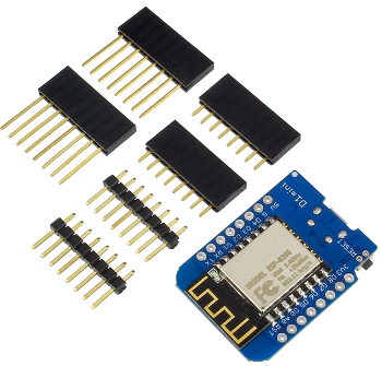
You also need to use a chip that handles Wi-Fi. I normally use PIC chips but none of the ones I had contained a Wi-Fi radio. So I looked at alternatives and chose an ESP8266 based module called a D1 Mini. This module can be programmed using the Arduino IDE via USB. It’s a little larger than most PIC chips, but is still a reasonable size.

D1 mini

A D1 mini doesn’t have any EEPROM–all of its memory is flash-based. However, there are libraries available which emulate EEPROM. So this is what I used to store the Wi-Fi credentials.

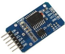
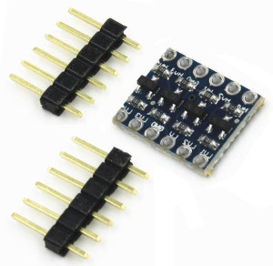
Once the NTP server has been asked for the time you need to be able to keep track of the time locally. NTP isn’t really suitable to do this by itself. So a real-time clock module or RTC is used. Previously I had used a DS1307 which seemed fine, but it wasn’t available to buy so I bought a DS3231 instead. This module is driven via an I2C bus. The D1 mini module also has I2C built-in. However the ESP8266 runs on 3.3 V and the DS3231 uses 5 V. So a level shifter is also needed.

Rtc4ch ls

The code to get the time and maintain it is lengthy but not complex and everything is sequential. When the ESP8266 starts a pin is checked to see if the Wi-Fi credentials should be asked for via the UART. If so, they are stored in the emulated EEPROM. The stored credentials are used to connect to the Wi-Fi. Then a packet is sent to the NTP server and the response is parsed to get the minutes and seconds of the current real time. None of the other time details are needed. The minutes and seconds are stored in the RTC module via the I2C bus. The time in the RTC may drift so the code occasionally retrieves the current time from the NTP server and updates the RTC. The code then loops waiting for the start of an even two-minute interval and transmits the WSPR tones. More about this in a later post. I’ll post the code then too.

Switchable LPF Response

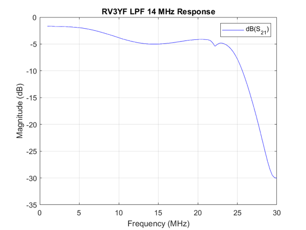
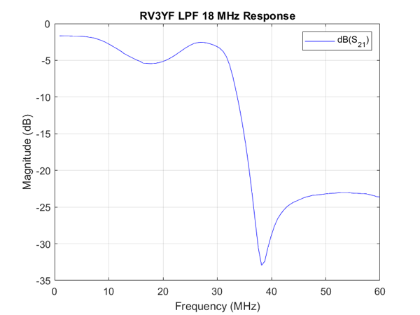
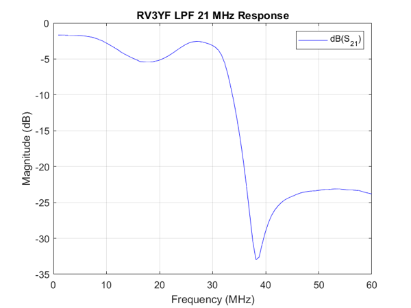
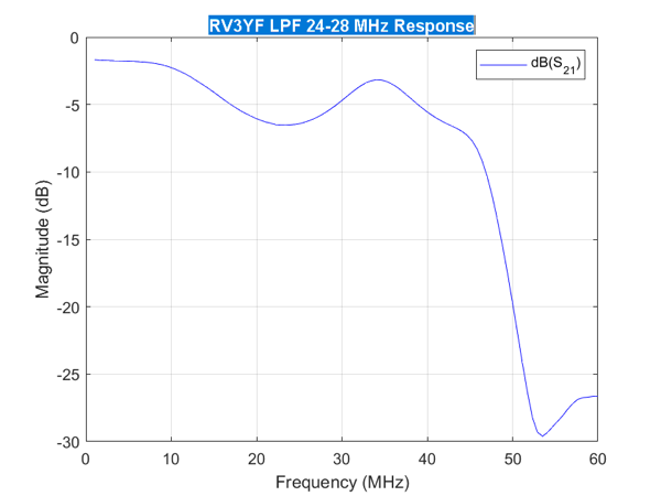
The switchable LPF for my WSPR Transmitter finally arrived and I’ve made some response graphs to test how it performs.

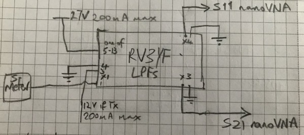
Test setup for Switchable LPF

The obvious bit of test kit to check out the LPFs is my nanoVNA. I suggest you buy a nanoVNA from a reputable dealer as there are plenty of clones which don’t work as well as the original.

The test setup is above. The 27 V in the drawing can go as low as 13.8 V, but will not work at any lower voltage. 

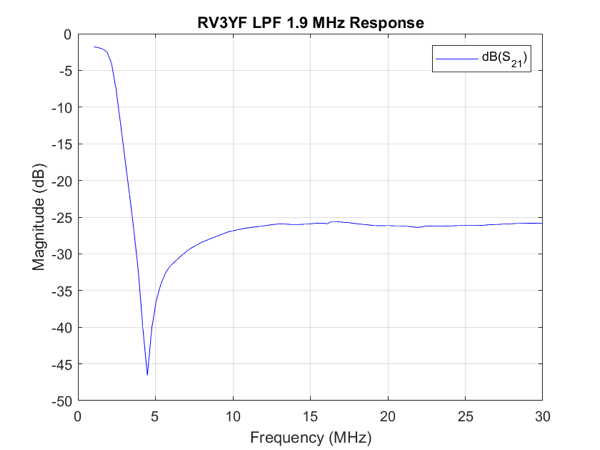
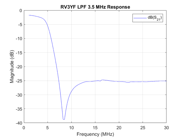
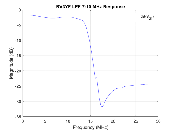
As I’ve mentioned before I find the small screen on the nanoVNA difficult to control with my clumsy hands. So I wrote another simple MATLAB script ajfLogMagS21 to drive the nanoVNA to get the response charts. The calibration done as before using my ajfCalibrate MATLAB script. The LPFs will attenuate the harmonics by 25 dB which will be enough for my feeble WSPR output.

RV3YF LPF 1 9 MHz Response

RV3YF LPF 3 5 MHz Response

RV3YF LPF 7 10 MHz Response

RV3YF LPF 14 MHz Response

RV3YF LPF 18 MHz Response


RV3YF LPF 21 MHz Response

RV3YF LPF 24 28 MHz Response

The next step is work out how to drive the switching of the bands. First thoughts are to send commands via I2C and have something convert that to a 13.8-27 V signal on the appropriate pin. I2C is attractive as I already have an I2C bus in the WSPR Transmitter.