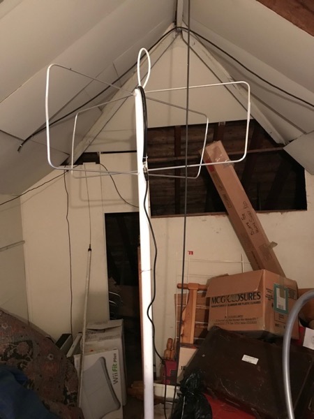
The Cebik Moxon is made up of four driven elements, two reflectors, a phasing line and a matching line.
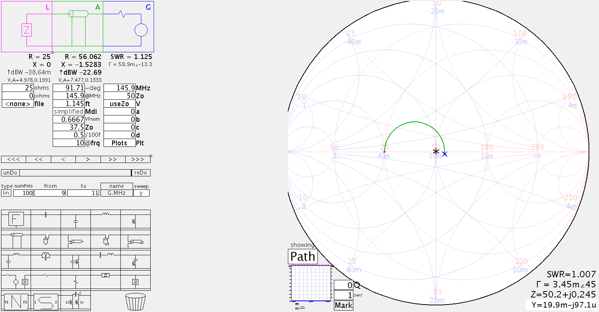
The matching line is needed to match the 25Ω impedance presented by the aerial to the 50Ω impedance expected by the coax feed to the radio. It is made up of parallel quarter-wave lengths of 75Ω cable. I modelled this in an excellent application SimSmith by AE6TY to see how critical its length is (the answer being not very much). The SWR is 1.125 at 351mm, and only rises to 1.13 at 330mm and 354.5mm.
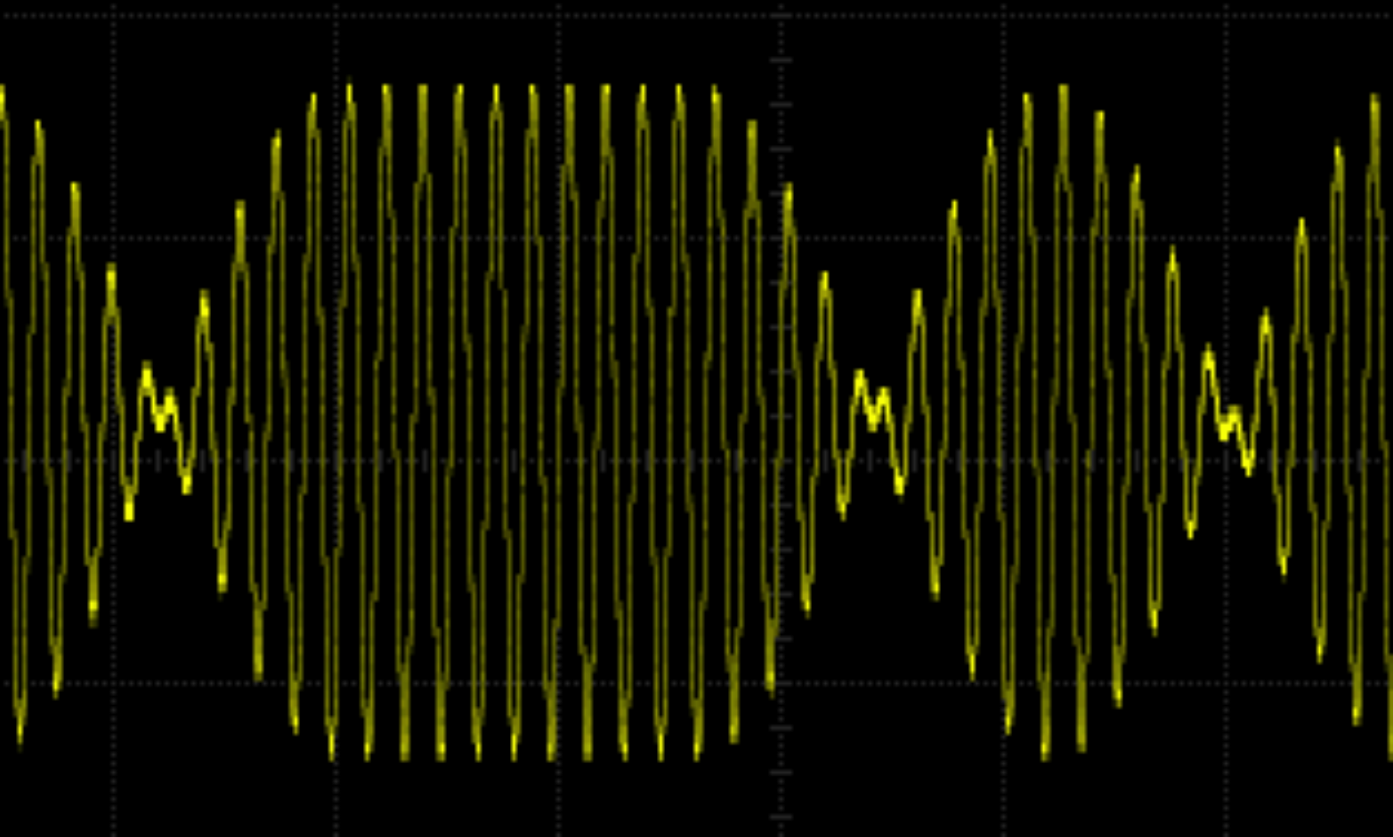
I worked out the velocity factor of the RG59U 75Ω cable (bought from Bitsbox who were very prompt and helpful but didn’t know its velocity factor) by building a TDR out of a circuit to make a fast pulse and my HP54615B scope. As usual Alan, W2AEW came to the rescue with this video #88: Cheap and simple TDR using an oscilloscope and 74AC14 Schmitt Trigger Inverter.
Here are my sums to work out the velocity factor of the RG59U cable measured with the TDR circuit.
5m takes 48.8ns between peaks, so the signal takes ![]() to go 5m which is 4.88ns/m, so the speed is
to go 5m which is 4.88ns/m, so the speed is ![]() , so the Velocity Factor,
, so the Velocity Factor, ![]() .
.
Using EE Toolkit on iPhone, in air ¼ ![]() is 513.7mm at 145.9MHz.
is 513.7mm at 145.9MHz.
So ¼ ![]() should be 513.7 x VF = 350.857mm.
should be 513.7 x VF = 350.857mm.

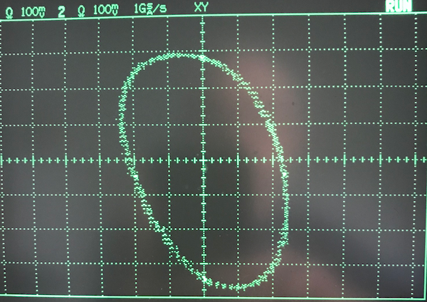
The phasing line is just a quarter wavelength of 50Ω cable which feeds the other element 90° out of phase from the first. Here’s an XY scope picture of the phasing.

It should be a bit more upright but I think that is probably due to the way I’m connecting it to the scope rather than the phasing line itself.
Now the bit I am particularly bad at: putting it all together.
I made the elements out of 6mm aluminium round tube. The tube is easy to cut with a hacksaw and to bend using a pipe bender. The matching section and phasing line are connected to the rods using solder tags and screws. The driven elements and reflectors are kept apart by whittled pea sticks. This distance between the driven elements and the reflectors is the most critical measurement. The pea sticks are held in place with shrink wrap and friction. The elements are hot-glued to a plastic drain pipe. This is not very robust, but works as long as the aerial isn’t disturbed too much. I’ll have to fix this properly if I want to move the aerial from the attic to the garden.

