70cms Cebik Moxon Aerial for LEO Satellites

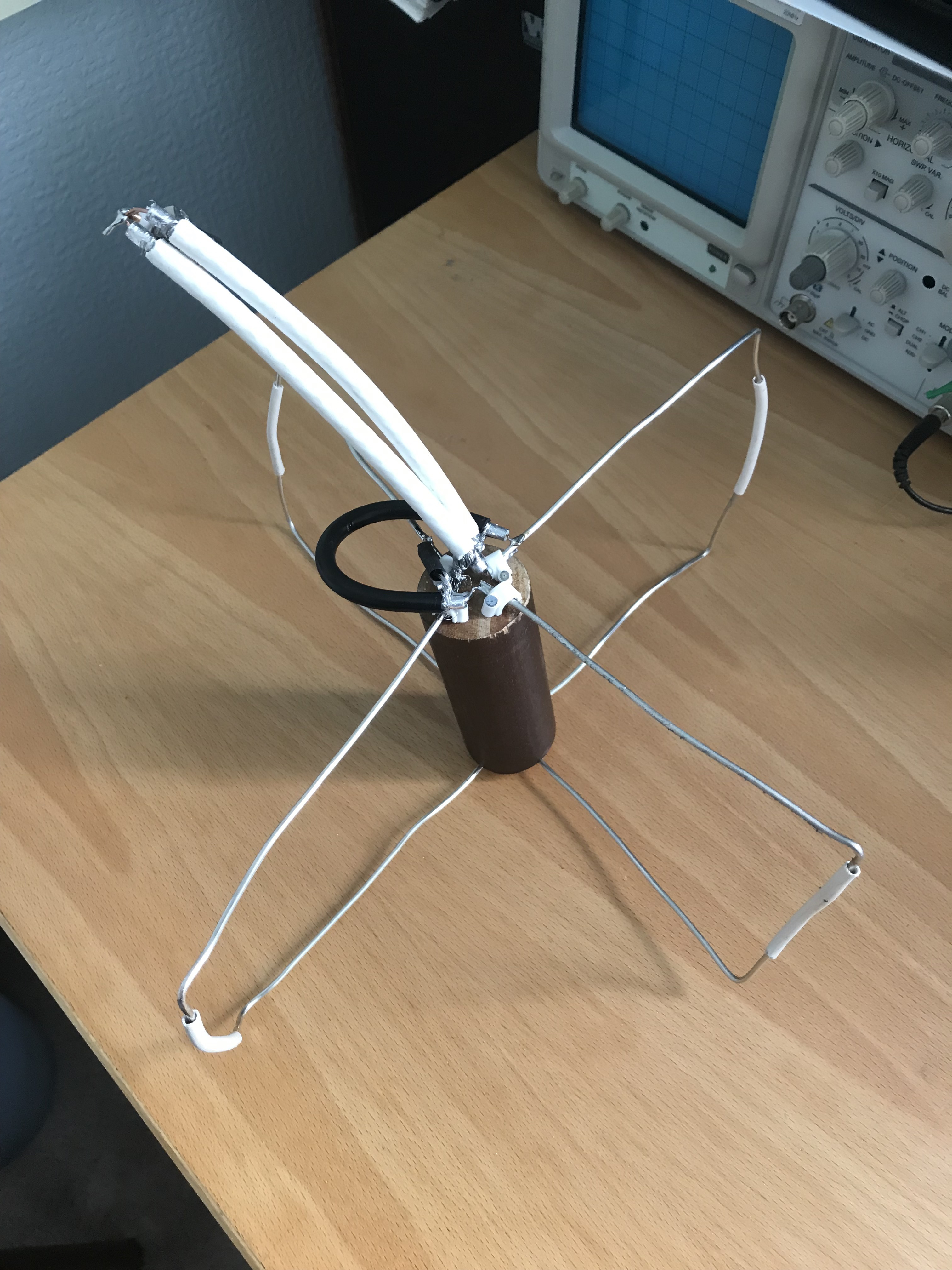
The 70cms (435MHz) version of the Cebik Moxon is now built and shows an SWR of 1.1 in the shack as measured with my AW07A antenna analyser. Hopefully this SWR will not change too much when I put in in the attic.

The elements are made out of #12 AWG wire from RS Components. The sizes are as specified in Cebik’s original article published in the ARRL QST in August 2001 “A Simple Fixed Antenna for VHF/UHF Satellite Work”. The phasing line is built as for the 2m version using RG59U coax cable from BitsBox only using a length for the 70cm band. The matching line is made from old 75Ω cable TV cable again at 70cm band length. The elements and lines are explained in my earlier post about ‘Building the 2m Cebik Moxon’.

The elements are stapled to an old wooden curtain pole to keep the driven elements and reflectors apart. At the ‘floating’ end they are kept apart using the insulation from old multi-core telephone cable and the shaft from cotton buds. I’ll hot-glue these in place once the aerial is in the attic. The distance between these floating ends is the most critical in the whole aerial.

LL0foAdTSrmGQ6ghONMY2A

I plan to use this aerial with the 2m version and suitable diplexers to communicate with U/V or V/U LEO satellites. Watch this space!

SSTV Award

The International Space Station transmitted some slow-scan TV images during February 2019. My 2m Cebik Moxon in the attic was easily able to receive these images even at quite low elevations. No need to be outside pointing a Yagi in the February chill!

ISS NOTA SSTV PD120 20190210 164147
SSTV Image from ISS

The images I received can be seen in the ARISS SSTV Gallery. You’ll need to put in my callsign: MM0GYG.

They handed out awards too.

Diplome

Great fun!

Satellite Aerial Link Budget

I’ve had a little luck transmitting to a satellite. I’m using packet as I can use the 2m Cebik Moxon aerial for both transmit and receive. To see if the ISS should be able to hear my signals I wrote a link budget program in Racket. There’s a few assumptions in it but it seems to confirm the ISS should have no problem hearing me on 2m. The program shows:

Transmit power (W)?
5
Frequency (MHz)?
145.825
Elevation (°)?
40
Transmit power:   5 W (36.99 dBm)
Frequency:        145.825 MHz
Satellite height: 403 km
Elevation angle:  40°

Satellite is 5396 km away
Signal at satellite is 9 dB above noise

This seems borne out as I do receive what seem to be digipeated packets just after I transmit them. But I can’t confirm on the ISS site that they are real and not just an echo from somewhere.

70cms doesn’t look as good:

Transmit power (W)?
5
Frequency (MHz)?
435.255
Elevation (°)?
40
Transmit power:   5 W (36.99 dBm)
Frequency:        435.255 MHz
Satellite height: 403 km
Elevation angle:  40°

Satellite is 5396 km away
Signal at satellite is -0 dB above noise

Increasing the power to 25W might work:

Transmit power (W)?
25
Frequency (MHz)?
435.255
Elevation (°)?
40
Transmit power:   25 W (43.98 dBm)
Frequency:        435.255 MHz
Satellite height: 403 km
Elevation angle:  40°

Satellite is 5396 km away
Signal at satellite is 7 dB above noise

I’m currently building the 70cms version and will try some FM voice contacts.

Here’s the link budget program:

#lang racket
; link budget for Cebik Moxon in attic
; Andy Fletcher Jan 9, 2019 

;
; definitions
;
(define (get_user_input prompt)
  (begin
    (displayln prompt)
    (string->number (read-line))))

(define (log10 n)
  (/ (log n) (log 10)))

(define (watts2dbm w)
  (* 10 (log10 (* w 1000))))

(define (degrees2radians d)
  (* (/ pi 180) d))

(define (square x)
  (* x x))

; distance to satellite in km
(define (satellite_distance e_degrees height)
  (let* ([e (degrees2radians e_degrees)]
         [earth_radius 6371]    ; kms
         [r (+ height earth_radius)] ; distance between geocentre and satellite
         )
    (sqrt (+ (square (* earth_radius (cos e))) (square r) (- (square earth_radius)) (- (* earth_radius (cos e)))))))

; free space path loss
(define (fspl f d)
  (- (+ (* 20 (log10 f)) (* 20 (log10 d)) 32.45)))

;
; execute
;
(let* (
       [ptx_watts (get_user_input "Transmit power (W)?")]
       [f         (get_user_input "Frequency (MHz)?")]
       [e_degrees (get_user_input "Elevation (°)?")]
       [h 403]               ; satellite height in kms
       [cable_loss -3.55]    ; measured dB
       [tx_gain 6.0]         ; Cebik Moxon modelled gain in dB
       [roof_loss -6.0]      ; assumed loss of signal going through the roof in dB
       [rx_gain 2.0]         ; assumed receive gain at satellite in dB
       [sat_max_sens 124.0]  ; assumed satellite maximum sensitivity in dBm
       [distance_to_satellite (satellite_distance e_degrees h)]
       [ptx (watts2dbm ptx_watts)]
       )
  (begin
    (printf "Transmit power:   ~a W (~a dBm)\n" ptx_watts (~r ptx #:min-width 1 #:precision 2))
    (printf "Frequency:        ~a MHz\n" f)
    (printf "Satellite height: ~a km\n" (~r h #:min-width 1 #:precision 0))
    (printf "Elevation angle:  ~a°\n" e_degrees)
    (printf "\nSatellite is ~a km away\n" (~r distance_to_satellite #:min-width 1 #:precision 0))
    (printf "Signal at satellite is ~a dB above noise\n"
            (~r  (+ ptx cable_loss tx_gain roof_loss (fspl f distance_to_satellite) rx_gain sat_max_sens) #:min-width 1 #:precision 0))))

Building the 2m Cebik Moxon

The Cebik Moxon is made up of four driven elements, two reflectors, a phasing line and a matching line.

The matching line is needed to match the 25Ω impedance presented by the aerial to the 50Ω impedance expected by the coax feed to the radio. It is made up of parallel quarter-wave lengths of 75Ω cable. I modelled this in an excellent application SimSmith by AE6TY to see how critical its length is (the answer being not very much). The SWR is 1.125 at 351mm, and only rises to 1.13 at 330mm and 354.5mm.

I worked out the velocity factor of the RG59U 75Ω cable (bought from Bitsbox who were very prompt and helpful but didn’t know its velocity factor) by building a TDR out of a circuit to make a fast pulse and my HP54615B scope. As usual Alan, W2AEW came to the rescue with this video #88: Cheap and simple TDR using an oscilloscope and 74AC14 Schmitt Trigger Inverter.

Here are my sums to work out the velocity factor of the RG59U cable measured with the TDR circuit.

5m takes 48.8ns between peaks, so the signal takes \frac{48.8}{2} = 24.4ns  to go 5m which is 4.88ns/m, so the speed is  \frac{1}{4.88ns/m} = 204.918 \times 10^{6} m/s, so the Velocity Factor, VF = \frac{204.918 \times 10^{6}}{c} = 0.683.

Using EE Toolkit on iPhone, in air ¼ \lambda is 513.7mm at 145.9MHz.

So ¼ \lambda should be 513.7 x VF = 350.857mm.

SmithMatching37z5line
SimSmith Matching Line

The phasing line is just a quarter wavelength of 50Ω cable which feeds the other element 90° out of phase from the first. Here’s an XY scope picture of the phasing.

Lissajous of phasing

It should be a bit more upright but I think that is probably due to the way I’m connecting it to the scope rather than the phasing line itself.

Now the bit I am particularly bad at: putting it all together.

I made the elements out of 6mm aluminium round tube. The tube is easy to cut with a hacksaw and to bend using a pipe bender. The matching section and phasing line are connected to the rods using solder tags and screws. The driven elements and reflectors are kept apart by whittled pea sticks. This distance between the driven elements and the reflectors is the most critical measurement. The pea sticks are held in place with shrink wrap and friction. The elements are hot-glued to a plastic drain pipe. This is not very robust, but works as long as the aerial isn’t disturbed too much. I’ll have to fix this properly if I want to move the aerial from the attic to the garden.

Cebik in attic
Aerial in attic

Cebik Moxon Aerial and Packet

When used with my FT–60 transceiver handheld, which is FM only, the Cebik Moxon picks up satellites AO–85, NO–84, AO–91, AO–92 and ISS SSTV. I don’t know enough about satellites to know if it’s getting good signals but I can hear many voice stations, amongst them G0VHS, EA7IFT, G0IIQ, OH1ON, EB2DJ, G0FGX, PE1NIL.

Using DireWolf and Xastir as described in my FT60 PTT page, we get

NO 84 Map
A map of stations