
I realised that now I’ve made a CW Sidetone Oscillator, a Morse Keyer and a Morse Decoder, I could make a useful tutor for testing my sent morse.
The trick of sending good morse is in the timing. Getting the inter-character and inter-word gaps the correct length is quite difficult especially at higher speeds. So a tutor to check this could be a big help.

So I lashed this together using a breadboard to do the connections.

And tested it as seen in this video: Morse Tutor Demo.mov.
As you can see it’s very rough and ready. If I were to make a proper version I’d remove the WPM and tuning aid on the top line which aren’t necessary. It would fit into a small box quite easily.
It was fun to throw together!
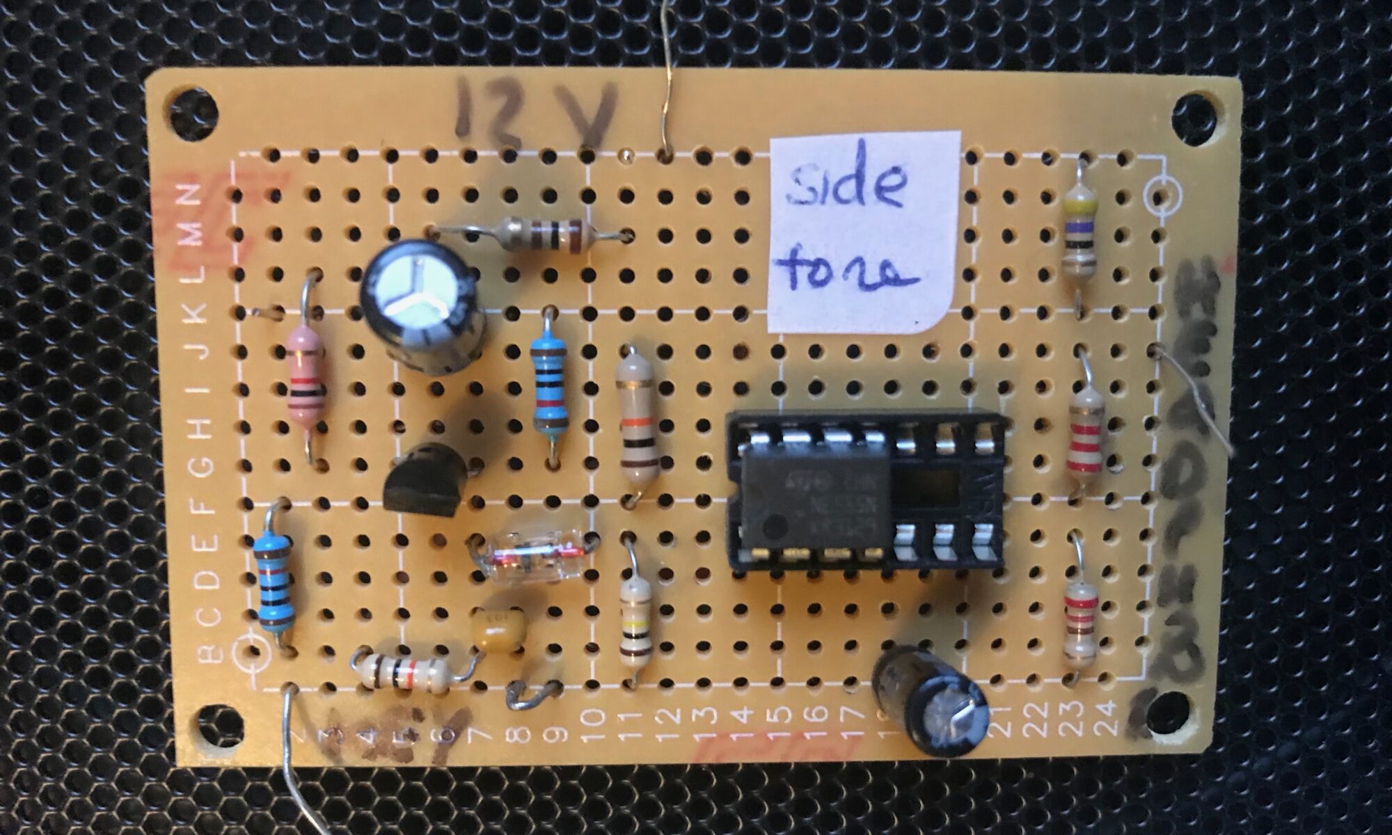

 The circuit works as follows. The morse key is attached to the JP1-KEY pin and when the key is keyed it grounds R2 making Q1 switch on. The 555 timer is configured as a multivibrator triggered through D1. The square wave output goes to JP2-HEADPHONE pin.