WSPR Transmitter–Code and Development

The WSPR Transmitter has, of course, firmware code. The D1 Mini runs most of the code, with the PIC12F1640 running the LPF driver. I hold the source code in a git repository on a local server.

The D1 Mini code was developed on a Raspberry Pi 4 mostly using Arduino CLI and vi. I used a couple of helper shell scripts (ardcomp and ardup below) to compile and upload. There are a couple of libraries required: ESP8266 and HCRTC. wspr_rtc_ad9850.ino takes about 19s to compile on Raspberry Pi 4, which is about twice as fast as a Raspberry Pi 3B+. 

ardcomp: 
arduino-cli compile --fqbn esp8266:esp8266:d1_mini_clone $*
ardup: 
arduino-cli upload -p /dev/ttyUSB0 --fqbn esp8266:esp8266:d1_mini_clone $*

I used a Raspberry Pi 4 because I like to protect the USB ports on expensive computers from the possibility of smoke due to any misadventures I may cause. See my previous post.

The PIC code was developed using MPLAB on an HP14S laptop running Windows 10. The USB port is protected (hopefully) by the PICkit 3 dongle that is needed to program the PIC. I’m not a great fan of MPLAB but, once you realise you can ignore all the marketing, it suffices.

The source is in this ZIP file. It’s at the stage it was when I made smoke. The code was working–it was the power supply circuit that was faulty!

My previous posts explain the code.
WSPR Transmitter — Transmitting WSPR Tones

This is a follow-on from WSPR Transmitter — keeping time.

Every two minutes the transmitter code optionally transmits a message as a sequence of WSPR tones.

First the frequency to transmit on is decided—this is a round-robin though the amateur HF bands. Whether a frequency is transmitted on was decided during the initial configuration via a UART connection. The decisions were stored in EEPROM and copied to ESP8266 memory from there.

The LPF is configured to filter appropriately for this frequency. More on this is a later post.

A random offset is added to the transmit frequency to minimise collisions with other transmissions. 

The tones are then transmitted which takes most of the two minute interval. The tones to be transmitted have been compiled into the code as an array using a useful tool. Thanks Scott! The tones are for particular output power. If the output power were changed the code would need to be recompiled. The AD9850 frequency tuning word (FTW) is loaded with the frequency (RF + AF) that is to be transmitted. The code waits for the length of a tone and repeats for subsequent tones. When all the tones to be transmitted in this interval have been transmitted the AD9850 FTW is loaded with zero which stops the AD9850 from transmitting.

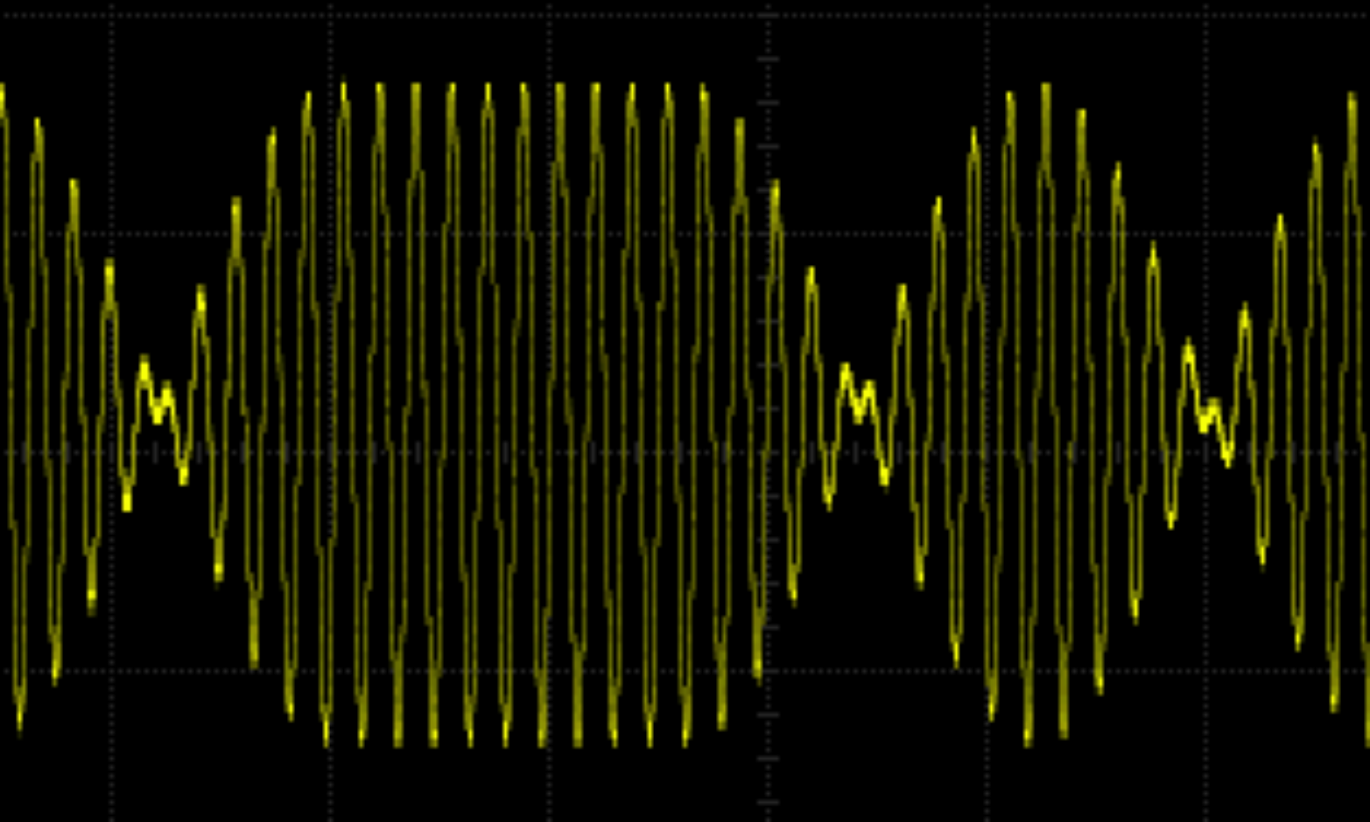
The AF tone part of the frequency is according to the WSPR User’s Guide Appx B: The keying rate is 12,000/8192 = 1.4648 baud. The modulation is continuous phase 4-FSK with a tone separation of 1.4648 Hz. It occupies 6 Hz. Continuous phase means the phase isn’t set to zero at the start of a symbol. 4-FSK means it uses four tones.

With an AD9850 reference clock of 125 MHz you get 125^6 / 2^32 = 0.0291 Hz resolution. For WSPR we want 1.4648 Hz or better resolution so the reference clock can be as low as 125^6 x (0.029 / 1.4648) = 2.4836 MHz. The AD9850 can cope easily with this requirement.

Next up is how the LPF band switching is carried out …

Bit Banging on PIC12F683

The PIC12F683 Microcontroller comes in a useful 8 pin DIL package. I favour this over smaller devices as it allows my ageing eyes to cope with connecting it to the rest of the circuit.

However, this PIC does not come with a UART and so any text debug needs to be output using ‘bit-banging’. I needed to debug a PWM motor drive so I tried to find an existing implementation of bit-banging on this or similar PICs developed in C but couldn’t find any. So here’s my solution.

This code allows communication at 9600 baud only. This is a reasonable speed for text debug as it allows fairly rapid output but won’t be too fast for any modern computer. The output is digital high and low on the GP0 pin. So highs will be at the supply voltage (Vdd) and lows will be at 0V. For this PIC Vdd is from 2 to 5.5V. I did all my testing with a 5V supply. The communication is 8-bit, no parity and one stop bit (8N1 for short). The remote UART used in testing was a Dangerous Prototypes’ Bus Pirate. The text was displayed on a Mac mini terminal using GNU screen: screen /dev/tty.usbserial-A9048DB4 115200,cs8,-parenb,-cstopb,-hupcl.

The code uses timer 1 as a counter to work out how long to keep the signal high or low. This means the timing of the code you are debugging will be way off as the code does a lot of looping to check the counter registers. But if the code being debugged is timing critical you shouldn’t be using text debug anyway. In that case you are better off simulating, flashing LEDs or looking at signals with a ‘scope or logic analyser.

The meat of the bit-banging code is in the putcharGP0 function. This sets or resets the GP0 port depending on the value of the bit to be transmitted. After each set or reset the code loops waiting for 1/9600 = 104µs. This loop is in the ‘WAIT_SYMBOL_TIME’ macro. This macro takes an argument which allows the loop to be adjusted allowing for the time taken to run the code between each bit. The macro is called ‘WAIT_SYMBOL_TIME’ as in this case each symbol is a single bit. Each character has a start bit, 8 data bits and a single stop bit. 

The code is built using this make file which uses Microchip’s xc8 C compiler and programs the PIC using a PICkit2.