Andy Fletcher Homebrew
PIC-based VFO using an AD9851
I’m playing with PLLs as part of my PSK Modem project and I need to inject some precise square wave signals into a PLL so I can characterise it. However, my faithful workhorse the TG120 function generator is analogue and is none too precise as the frequencies are set using potentiometers. The function generator on my GOS–620FG ’scope has the same problem.
I had a spare AD9851 DDS module which I had bought to try with my Aerial Analyser project which I discarded in favour of a Si5351a. I had already written the difficult bit of driving the AD9851 for a demo as part of that project so, with a little recoding to read in the frequency to oscillate at, a pad board and a few components and pins, this VFO was born.
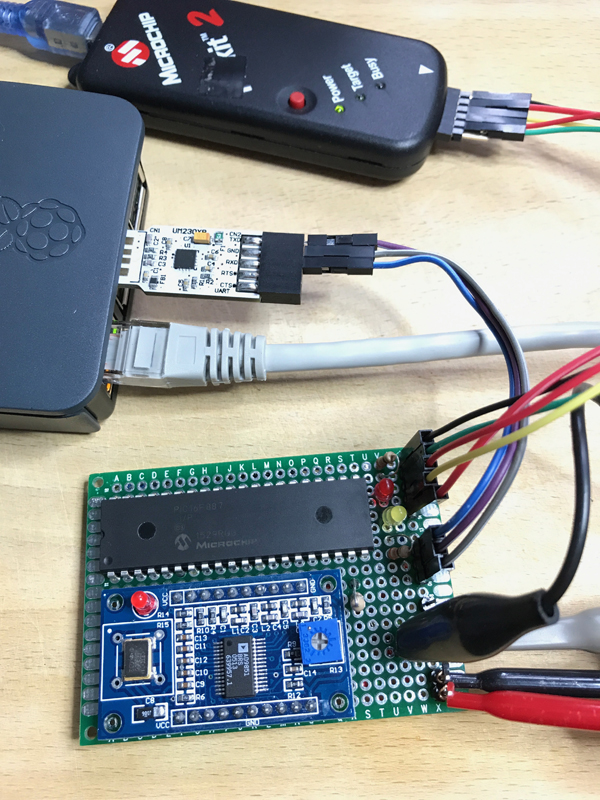
The PIC16F887 loops prompting for and then reading the frequency from the UART. For each new frequency it serially loads the AD9851 DDS with the appropriate word. Four signals are presented at the RF Out pins – 2 square waves (true and complement), a sine wave and a filtered sine wave. I use a Raspberry Pi with a UM230XB UART USB dongle to drive the other end of the UART and call screen /dev/ttyUSB0 19200,cs8,-parenb,-cstopb,-hupcl to answer the prompts, but any UART running at 19,200 baud will do. The RF out pins should probably be SMA or BNC, but I didn’t have room on the board. However, the sine wave looks good up to 60MHz and the square wave is good up to about 5MHz. This will be fine for testing the PLL as it needs inputs between DC and 50kHz.
Here’s my scribble of the layout:
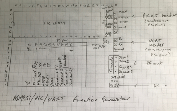
The PICkit header is only used to program the PIC.
I used a PIC16F887 because I had one to hand. A smaller PIC (in physical as well as memory size) would do just as well. Note that the code would need to be tweaked for a different PIC.
The C code is in this ZIP file along with the make file.