Andy Fletcher Homebrew
Aerial Analyser
Here are some notes, a few photos and a few scribbled diagrams about my Aerial Analyser project. I hope it is interesting, and perhaps useful.
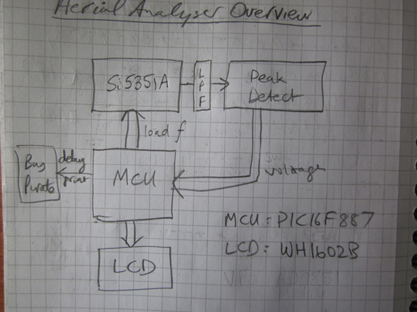
The aerial analyser is built around VK5JST’s peak detector and linearisation circuit, feeding into a PIC16F887 MCU which calculates and displays the results on a 2 x 16 character LCD display and also controls an Si5351A as the VFO.
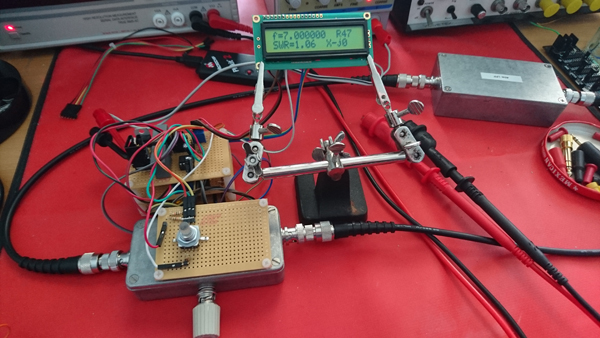
The project is built on pad boards (with ground plane ugly-style for the RF bits).
Although I intended the aerial analyser to work from 3MHz to 52MHz, I haven’t tested it much above 10MHz. Next test will be done once I’ve built a decent 6m LPF which has a low insertion loss.
RF Section
The RF section is made up of an Si5351A breakout board (from AdaFruit, I didn’t know about the QRP Labs board when I bought it), the peak detector and a suitable LPF. The Si5351A and peak detector are housed in a metal box which has three BNC sockets. The square wave signal generated by the Si5351A is fed to one socket, to be connected to a suitable LPF for the frequencies in use and is thus converted to a sine wave. This sine wave is fed back into the box via one of the other BNC sockets. The other BNC socket is used to connect the device under test (DUT). The DUT is probably an aerial.
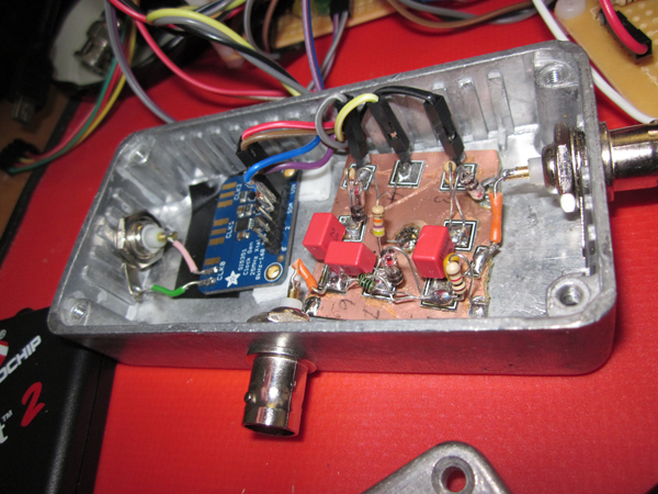
The detector is the same as VK5JST’s original. I used 1N34A diodes.
Detector Interface
The detector is presented to the MCU via a detector interface.
The detector interface schematic is almost the same as VK5JST’s detector interface. I had to clamp the \(V_{in}\) output using a Zener diode to avoid exceeding the PIC’s \(V_{dd}\). I also used different op-amps.
MCU
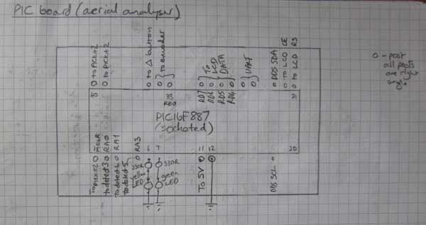
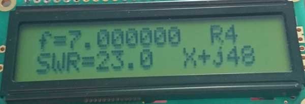
The MCU (see pin diagram) sits in a loop calculating the results, displaying them and handling changes to the required frequency. If a frequency change is wanted the Si5351A is configured to change the frequency. In any case, the detector voltages are then read and used to calculate the complex impedance and SWR of the load. These results are then displayed.
The PIC16F887 controls the Si5351A via an \(I^2C\) interface driven by an Si5351A driver.
The Si5351A driver is a port from Hans Summer’s Arduino-based driver which you can find on Hans’ site and the QRP Labs site. Hans’ site is a wonderful resource for radio and electronics experimenters and I can’t recommend it too highly. QRP Labs make a Si5351A Synthesizer kit which contains a pre-soldered Si5351A chip, 3.3V regulator, and \(I^2C\) level converters. Thanks Hans!
I chose to use a DDS rather than a VFO so the frequency could be controlled programmatically. This allows the MCU code to determine the sign in the complex impedance \(R \pm jX\), by changing the frequency briefly and seeing if the impedance becomes more inductive or capacitive.

I originally chose an AD9851 for the DDS. See Linearity Problems below. The AD9851 provides \(1V_{p-p}\) and the detector requires \(3V_{p-p}\) and I spent a lot of time trying to solve this. As all I wanted was a voltage amplification and not power, I thought a broadband transformer would do, but I couldn’t make one that was linear across 3MHz to 52MHz. Then I looked at BJT/FET amps briefly and decided that was too difficult for just now. I ended up with a current feedback op amp (an LMH6703) which is spec’ed as linear up past VHF. However, I couldn’t get it to be linear past 40MHz. So I changed to using an Si5351A which provides about \(3V_{p-p}\) out of the box. I have a great deal still to learn in this area!
The frequency is changed using a rotary encoder. A button in the encoder allows you to control how much the frequency is changed as you turn the encoder. The encoder turns are vectored to an ISR (interrupt service routine) which works out which way the encoder is being turned. During the main loop these changes are debounced before being used to determine the required frequency. It took me a while to find a rotary encoder which was suitable. I wanted one with a button and a threaded shaft so it could be screwed to the box. I finally found COM–10982 at HobbyTronics.
The results are shown on a Winstar \(2 \times 16\) LCD display supplied by Bitsbox. The display is driven by an eXtreme Electronics \(xAPI^{TM}\) module.
The LCD driver source is from eXtreme Electronics. Thanks Avinash! I removed the LCDWriteInt fn from it to save code space as I wasn’t using it. I also needed to configure the header to get it to use the correct PIC pins.
I amended the \(I^2C\) library from HobbyTronics’ \(I^2C\) library.
The source files for the MCU are listed below.
- Aerial Analyser
- Si5351A Driver
- I2C Interface
- The LCD driver is from eXtreme Electronics. These files are needed:
myutils.h,lcd_hd44780_pic16.c,lcd_hd44780_pic16.handcustom_char.h.
Software Development
I’ve written the Aerial Analyser code so that it can be compiled with the Microchip MPLABX IDE. But it can be built with a make file. So the software development cycle can be: edit with a favourite editor, compile with XC8 and program the PIC with pk2cmd, all driven by make.
Linearity Problems
I had problems getting the AD9851 to be linear enough across 3MHz to 52MHz (see chart), and the LMH6703 amp made it worse. So I replaced the AD9851 with an Si5351A. This is much more linear (see chart).
The two charts above were created using a Racket program to capture the data directly from my Rigol scope. Then an Octave script was used to create the chart. This is a much less laborious way to create such graphs than copying values manually from the scope screen. See more details on Rigol Capture. Ooops! the \(V_{p-p}\) axis is \(10\times\) out – I’m always making the Rigol scope probes switch from from \(10\times\) to \(1\times!\) Maybe I should tape them in \(10\times\) as I hardly ever use \(1\times\).
Demo Code
I made a couple of demo code modules (one for AD9851 and one for Si5351A) while playing with this project. Click on Software in the Site Menu to see them.
PSU
The power supply board just uses a 7812 to power the detector interface, and a 7805 for everything else. It used to have an ICL7660S to provide a dual rail supply for the RF amp, but I took it out (luckily it was socketed) because I wasn’t using it. The 7805 needs a heat sink.
Lessons Learnt
- making VFOs and RF amps broadband ain’t easy
unsigned longcode on an 8-bit MCU takes up a lot of space- don’t put a heat sink right next to an encoder spindle
- don’t put RF stuff on a breadboard
- there’s plenty more to learn
Saving Code Space on PIC
This project has ground to a halt because I ran out of code space on the PIC16F887 that drives it. I need more space to add sweeping the test frequency and output of swept data to UART (to allow a chart to be made on computer). The sensible thing to do would be to use a better PIC, but of course the sensible thing is not always the most interesting. I used the Microchip XC8 compiler (free version) to write the code for the aerial analyser, and you do get a message saying something like “spend money on our compiler licence and you’ll get more efficient code”. This option isn’t interesting either. So as an exercise I took a XC8 C code source I had used to flash LEDs and output some strings and 16-bit numbers to UART, and rewrote it in PIC assembler. I expected to get a reasonable decrease in code-space but I was mildly surprised at how just much I got. The C hex file took up 3784 words, and the assembler hex file only 1696 words.
The C code is in main.c.
The assembly code is held in three files:
Both hex files were built using MPLABX.
So I’m tempted to rewrite the Aerial Analyser in PIC assembler and use floats instead of longs. I only used longs to save code space as the XC8 compiler linked in more floating point code than was needed.