Andy Fletcher Homebrew
PSK Modem
Following on from the Hellschreiber Modem, I am building a PSK31 modem. I initially wanted to use MATLAB and Simulink with an Arduino so that I could concentrate on the signal processing aspects of the project, rather than getting bogged down in the implementation details. However, it is clear that the simulation on Arduino would not be able to run in real time so I’ve given up that idea. The modem will be made using analogue circuits.
The modem could be used when a computer is not wanted or available. I have dreams of running PSK in the garden on a Scottish summer’s day without squinting into a laptop screen. So the modem will comprise a bright display – and an umbrella to keep the rain off.
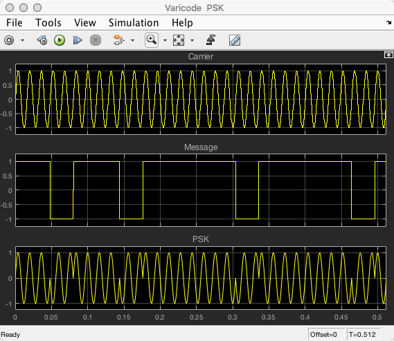
A BPSK31 signal has a carrier which is modulated by a sequence of varicode symbols representing the text of the message being sent. As the signal is binary a varicode symbol can be thought of as a bit. Each bit takes a specific time to be transmitted. The phase of the sequence is changed by 180 ° whenever the value of adjacent bits change. Here is a MATLAB scope view of the process:
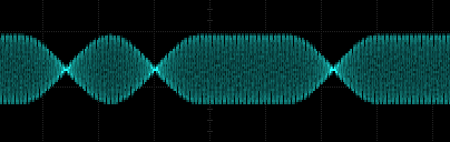
The signal is also low-pass filtered to avoid sudden changes in phase causing splatter. Here is an example signal created by fldigi:
In my implementation the modem will generate an audio BPSK31 signal containing the message which will be derived from varicode tables held in an MCP. I haven’t decided which MCP yet, but I tend to favour PICs and Arduinos. The code will be in C. That audio signal will be mixed with the RF carrier by an SSB transmitter.
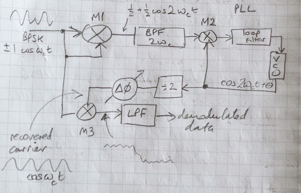
On receive, the receiver will pass the received audio to the modem which will recover the varicode sequence. The high-level demodulator design is taken from Horowitz, but I bear the blame for the low-level design. Here is the overall schematic
I haven’t thought much about how the modem will be operated, but in the first instance it will work on a fixed audio frequency and all the tuning will be done in the transceiver. The decoded text will be shown on a scrolling LCD. This means that using it will be more like listening for morse and fine-tuning to a wanted signal, rather than the computer-based waterfall clicking method. I have hopes that it will be more fun to hunt PSK31 this way.
Progress so far (is mixed)
I’ve designed and made a prototype of the modulator. Here is the circuit:
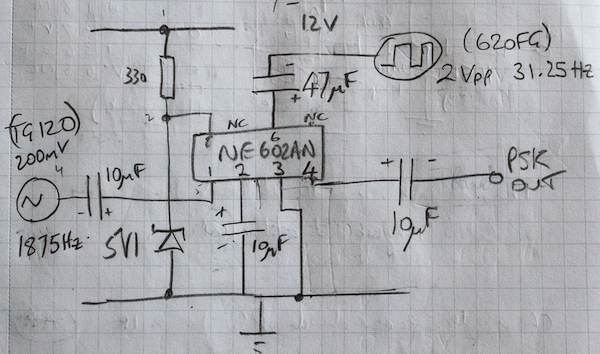
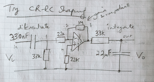
It is shaped using an CR-RC circuit:
The varicode is generated by a Simulink simulation running on an Arduino which sends it to a GPIO pin. Here is the resulting modulated signal:
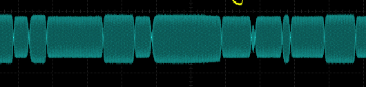
It may not be able to be decoded by a demodulator that was relying on amplitude modulation as the amplitude is a bit wonky compared to the example signal above. However, the message is decoded by fldigi almost entirely. Here is a decoded test message:
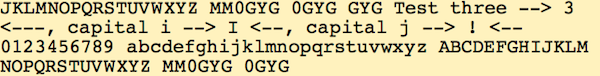
The main problem is because I’m using the varicode sequence as the modulating input in the NE602. In varicode, a capital ‘J’ has a long sequence of ‘one’ bits and when it is sent the frequency of the modulating input to the NE602 becomes very low because the phase doesn’t change. The frequency is probably lower than the NE602 design limits though this is not specified in the datasheet. Also some of the bits are short. The CR-RC shaping isn’t as neat as the raised cosine shaping used by fldigi and I’ll need to check the bandwidth. I’m going to stick with this design for just now and make a better design later. I don’t think it’s airworthy.
As far as the demodulator is concerned, I have implemented the first mixer OK (M1 in the overall design above). Here is the circuit:
The implementation of the VCO is easily tested by using a power supply to give the VCO input from 0V to Vcc.
I am currently bogged-down trying to make (my very first) PLL work properly. Here is the circuit so far:
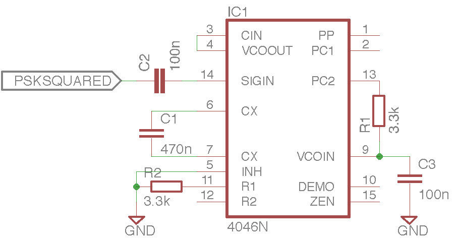
I am reading ‘Phase-Locked Loops’ by Roland Best so I can better understand my mistakes.
Or not.
I’ve pretty much given up on this – partly because it was much more difficult than I thought it would be. Also the FT8 mode seems to have made PSK31 traffic plummet. Maybe I’ll get back to it some day.
Or not.