Andy Fletcher Homebrew
Hellschreiber Modem
Hellschreiber is a fuzzy digital mode that works much like a fax machine. There is a lot of good information on the web which you can find with your favourite search engine. The information at Murray, ZL1BPU’s site is especially good. Thanks Murray!
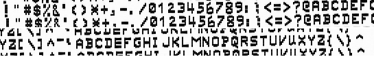
There are many types of Hellschreiber modes. The simplest to implement is Feld Hell which is a simple on-off keying design. A receive dot is ‘printed’ for each half-pixel that is transmitted. Each column is repeated below itself to allow for the receiver not being in sync with the transmitter. Like this:
I have implemented a PIC-based modem which can send and receive Feld Hell. When sending, the modem is used to key a transmitter using on/off keying. On receive the audio from a receiver is demodulated and the results are shown on an OLED screen. This means that the modem can be used with a transceiver to send and receive Hellschreiber without the use of a computer.
There is a switch to put the modem into transmit or receive mode. Characters for transmission can be typed while in receive mode.
Modulation/Transmission
The modem takes in the text to be transmitted via a UART and keys the dots to one of the PIC’s GPIO pins. This GPIO pin is connected to the tranceiver’s keyer input.
The example Feld-Hell characters above shows the characters the modulator can produce. The font was taken from the feldhell_fon.h file which is used by fldigi. It wasn’t in the form I wanted for the PIC so I converted it using a Racket program.
The UART is interrupt driven and uses a circular buffer which must be kept from becoming full by processing the characters received at the UART. In practice, my typing is slow enough that this wasn’t a problem in my testing. The buffer could be made bigger is it were a problem.
Each character received at the UART is presented at the keyer GPIO pin as a series of key-on or key-off signals to make the columns of the Hellschreiber character. Each on or off signal is keyed for the required Hellschreiber dot time.
Demodulation/Reception
The audio received by the modem from the transceiver is passed through a tone-detect circuit and presented as an binary signal at one of the PIC’s GPIO pins.
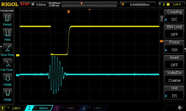
This receive pin is sampled once every Hellschreiber dot time and the sampled value is displayed as a dot (or a space) on the OLED screen (in Hellschreiber repeated column fashion as described in the intro). It would probably be better to oversample the dots, but there is not enough Hellschreiber traffic to be able to test this properly. I’ve left oversampling as a ‘matter for further study’.
The OLED is driven over a SPI.
Implementation
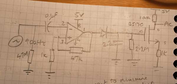
I laid-out the modem on a pad-board with pins for audio receive, keyer, UART and power.
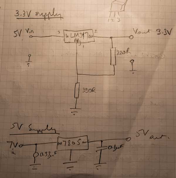
The power supply takes 7V and uses a 7805 to make a 5V ‘rail’ (it’s all spaghetti wiring). The 5V is also used by an LM317 to provide a 3.3V ‘rail’. Here’s some scribbles of the power supply schematic.
I used a PIC16F887 because I had one in my shack, on PORTB there are internal pull-ups which are useful for reading the switch. It also has enough memory for the Hellschreiber font table.
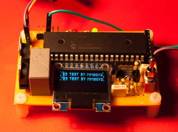
Here’s my lab-book scribble of the layout and a photo of the modem:
Demo Code
The PIC code is in assembler: demo code.
OLED Blues
I chose a SSD1306 128 x 64 Dot Matrix OLED (from the good people at Bitsbox) because it has built-in scrolling and was nice and cheap. It’s a reasonable size for the display, even with my aging eyes, and it works well. But the documentation is poor. The English is OK, but there is no good explanation of how the OLED memory is structured. You get really detailed info on each individual command, but little information at all about why or how you would use the commands. There is a sample flow-chart of how to set it up but only for simple use. I also looked at the libraries provided by some of the vendors and they all appear to be the same. You get an encapsulation of the commands but no good description of how to use them except in a rather simple demo. However, the libraries look good for straightforward use.
I wanted to have the received Hellschreiber scroll along the top half of the OLED and continue on the bottom half. I’m sure the OLED can do this for you, but I couldn’t work out how. This is a shame as the OLED is a useful bit of kit, but without understanding its internal structure you are forced to bit-map pixels thus using up valuable PIC memory.
Possible Enhancements and Changes
- display a bare-bones waterfall for tuning;
- use a (physically) smaller PIC – the PIC16F887 is a 40-pin PIC and I don’t use many of the pins;
- show each column as 14 dots: currently shown as 16 dots with two of them being empty. This is another one of the OLED Blues as I could get the 14 dots to display quite readily on a UART simulation of the OLED, but in the OLED itself I didn’t get the expected results;
- I am not inclined to write in PIC assembler again on a banked PIC. Next time I’ll used a PIC with a flat memory map, or some other microcontroller. (I hope I remember, as the sort of bug you get by being on the wrong page or bank is not easy to debug!);
- oversample on receive;
- continue the scrolling on the bottom half of the OLED.