Satellite Aerial
I thought it was about time I understood aerials more, so I have built an omnidirectional aerial for LEO satellite use.
I’m hopeful that I will be able to use the aerial in my attic, but if not I’ll use it in the garden. The aerial I’ve picked is documented in the ARRL Antenna Book in one of the supplementary PDFs. The article which describes it was published in QST in 2001 and is called “A Simple Fixed Antenna for VHF/UHF Satellite Work” by L. B. Cebik, W4RNL. I can’t link to it because it is copyrighted by ARRL but I explain most of it below. It is a pair of Moxon rectangles at 90° to each other.
I made a model of the aerial in the excellent Mac application cocoaNEC by Kok Chen, W7AY. The other aerial modelling applications I looked at were all based on spreadsheet tables. I found the programming approach used by cocoaNEC easier to use. Here’s the shape of the aerial as shown by cocoaNEC.

The driven elements are the top ones, and the reflectors are the bottom ones. Both have vertical parts which make up the Moxon rectangles. One of the driven elements is driven from the feeder through a matching line. The other driven element is driven 90° out of phase through a phasing line. This gives the radiation pattern below. This is the VHF version of the aerial. As you can see it is almost omnidirectional but favours elevations that you might expect to be able to use a satellite at.

This was output by this cocoaNEC program of the Cebik aerial. But see my remarks about reality below.
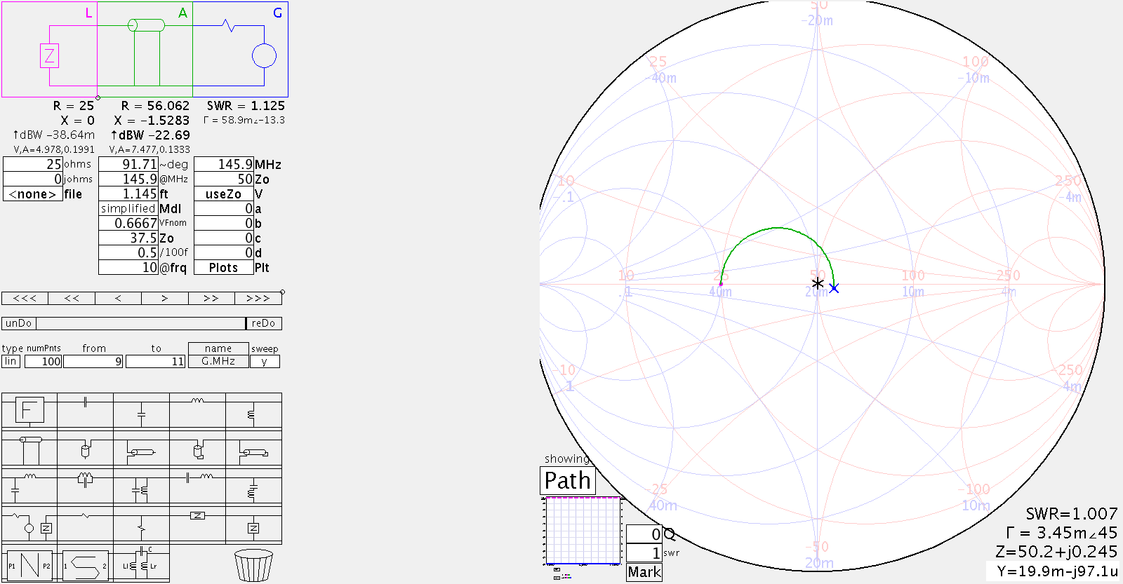
The matching line is needed to match the 25Ω impedance presented by the aerial to the 50Ω impedance expected by the coax feed to the radio. It is made up of parallel quarter-wave lengths of 75Ω cable. I modelled this in another excellent application SimSmith by AE6TY to see how critical its length is (the answer being not very much). The SWR is 1.125 at 351mm, and only rises to 1.13 at 330mm and 354.5mm.
I worked out the velocity factor of the RG59U 75Ω cable (bought from Bitsbox who were very prompt and helpful but didn’t know its velocity factor) by building a TDR out of a circuit to make a fast pulse and my HP54615B scope. As usual Alan, W2AEW came to the rescue with this video #88: Cheap and simple TDR using an oscilloscope and 74AC14 Schmitt Trigger Inverter.
Here are my sums to work out the velocity factor of the RG59U cable measured with the TDR circuit. 5m takes 48.8ns between peaks, so the signal takes \(\frac{48.8}{2} = 24.4ns\) to go 5m which is 4.88ns/m, so speed is \(\frac{1}{4.88ns/m} = 204.918 \times 10^6 m/s\), so the Velocity Factor, \(VF = \frac{204.918 \times 10^6}{c} = 0.683\). Using EE Toolkit on iPhone, in air ¼ 𝜆 is 513.7mm at 145.9MHz. So ¼ 𝜆 should be 513.7 x VF = 350.857mm.
The phasing line is just a quarter wavelength of 50Ω cable which feeds the other element 90° out of phase from the first. Here’s an 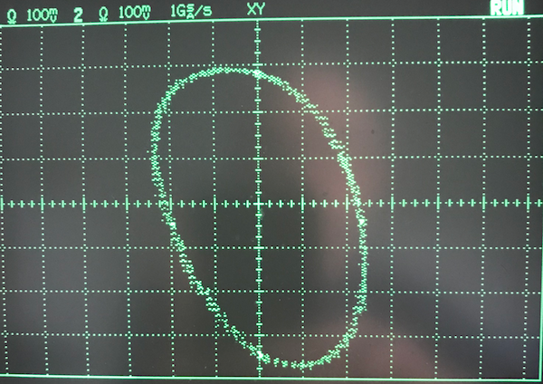 XY scope picture of the phasing. It should be a bit more upright but I think that is probably due to the way I’m connecting it to the scope.
I made the elements out of 6mm aluminium round tube. The tube is easy to cut with a hacksaw and to bend using a pipe bender. The matching section and phasing line are connected to the rods using solder tags and screws. The driven elements and reflectors are kept apart by whittled pea sticks. This distance between the driven elements and the reflectors is the most critical measurement. The pea sticks are held in place with shrink wrap and friction. The elements are hot-glued to a plastic drain pipe. This is not very robust, but works as long as the aerial isn’t disturbed too much. I’ll have to fix this properly if I want to move the aerial from the attic to the garden.
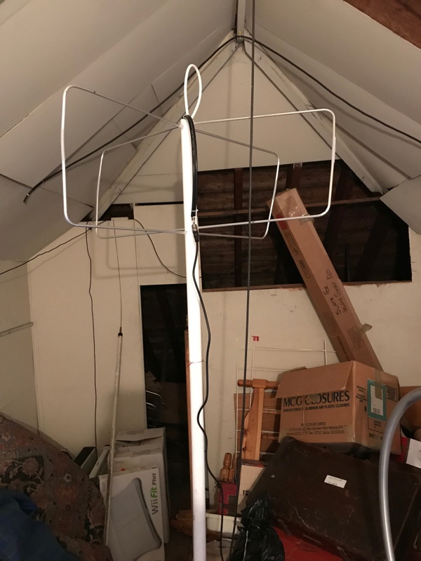
The aerial model above has at least one features that is impossible in the real world. The driven elements can’t be so close in a physical world. Also I want the aerial to be placed in the attic. My attic is about 30’ from ground. The aerial model below reflects reality. I suppose I could put down a ground plane in the attic, but I trip over enough things in the attic anyway.

The AW07A antenna analyser shows an SWR of 1.2 which seems good enough. The same SWR was measured at the transceiver and at the aerial.
The cable to the attic is RG58 and has a loss of 3.52dB so I’m considering putting in a masthead preamp. The cable loss was measured by sending the AW07A signal at 145.8MHz down it and measuring the RMS voltage at the HP 54615B scope. This was 194mV. The AW07A signal direct to the scope was 292mV. So the voltage loss was \(20log \frac{292}{194} = 3.55dB\).
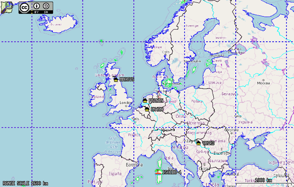
In conjunction with my FT–60, which is FM only, it picks up satellites AO–85, NO–84, AO–91, AO–92 and ISS SSTV. I don’t know enough about satellites to know if it’s getting good signals but I can hear many voice stations, amongst them G0VHS, EA7IFT, G0IIQ, OH1ON, EB2DJ, G0FGX, PE1NIL.
Using DireWolf and Xastir as described in my FT60 PTT page, we get
and a log of stations heard and decoded.
This has been a lot of fun!
Next step is to transmit to a satellite. I’ll try packet as I’ll be able to use the aerial for both transmit and receive.